Table of Contents
1
22
GROUP PROFILE
PRODUCT PRESENTATION
SOLUTIONS
REFERENCES
62
01
02
03
1.1 Standard Panel
2
2.1 Utility Scale
24
3.1 Utility Scale
64
1.2 Flexible/Light weight CIGS Panel
7
2.2 Distributed generation
27
3.2 Distributed generation
66
1.3 BIPV Panel
14
2.3 BIPV
29
3.3 BIPV
70
2.4 Flex Rooftop
34
3.4 Flex Rooftop
72
2.5 Vehicle and Yacht application
38
3.5 Vehicle and Yacht application
76
44
52
PRODUCT PRESENTATION
1.1
Standard Panel
1.1.1 MiaSolé CIGS Panel
1.1.2 Solibro SL2 CIGS Panel
1.1.3 Solibro SL2-F CIGS Panel
1.1.4 a-Si/uc-Si Panel
1.1.5 a-Si/Ge Panel
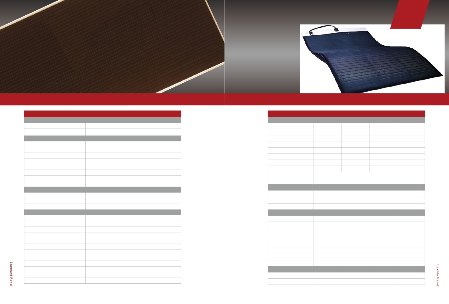
1.2
Flexible/Light weight Panel
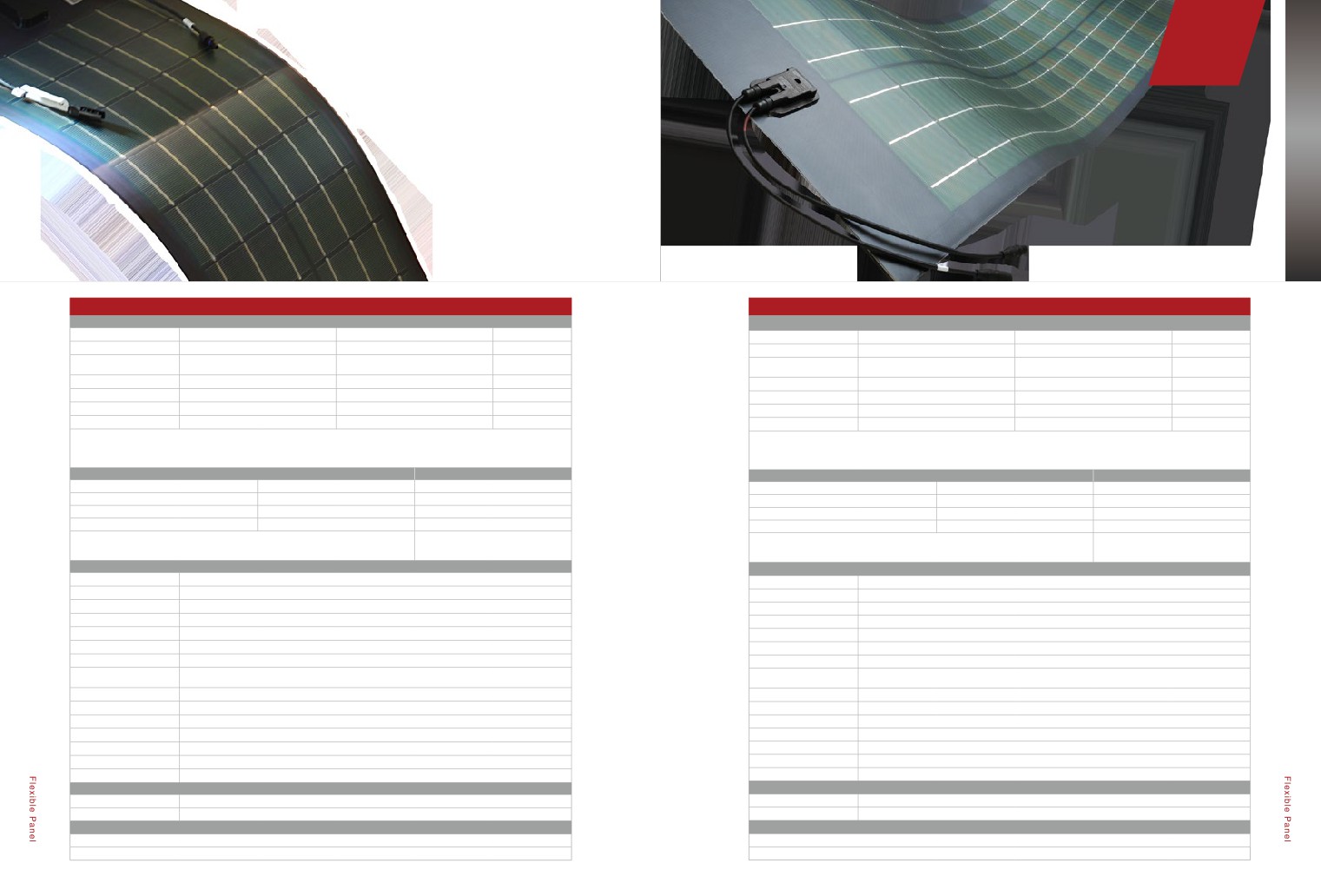
1.2.1 MiaSolé FLEX CIGS Panel
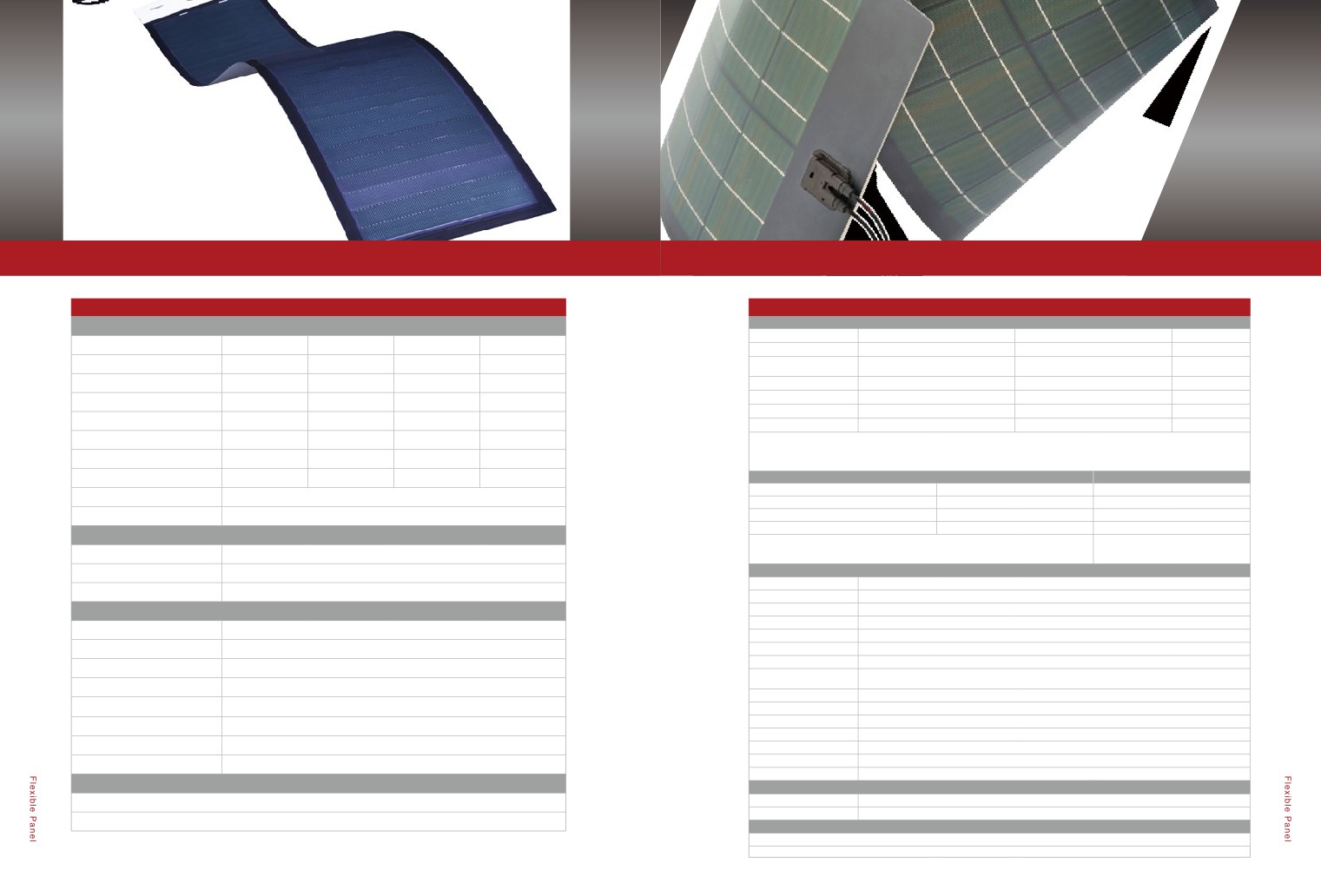
1.2.2 Global Solar PowerFLEX™ CIGS Panel
1.2.3 Light weight Panel
1.3
BIPV Panel
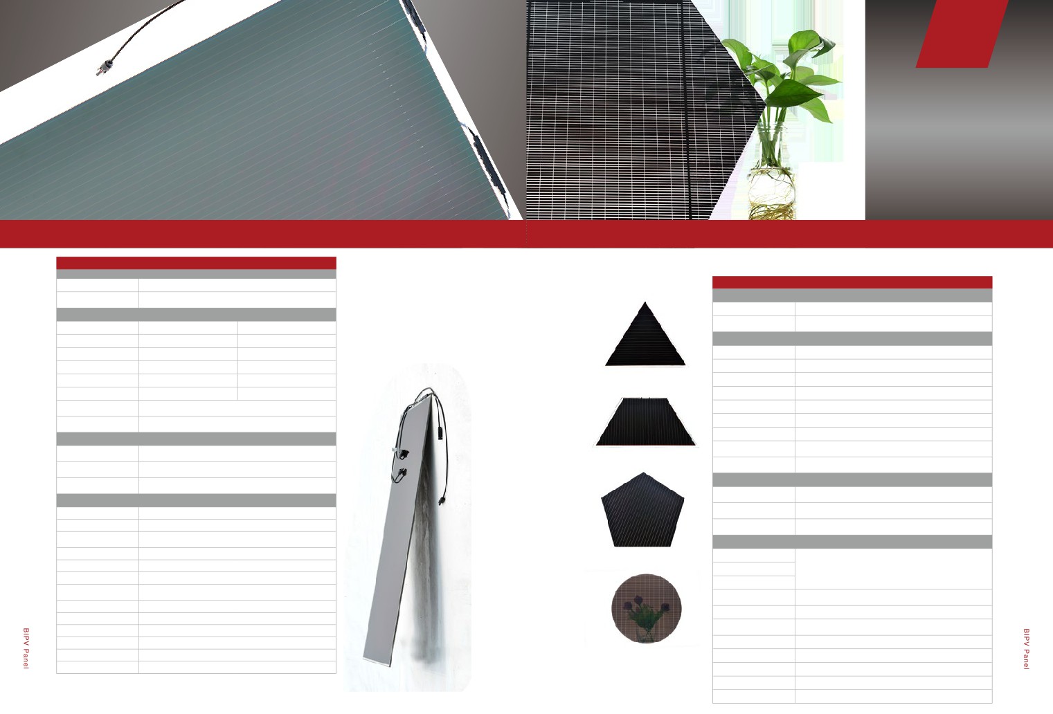
1.3.1 Back electrode translucent Panel
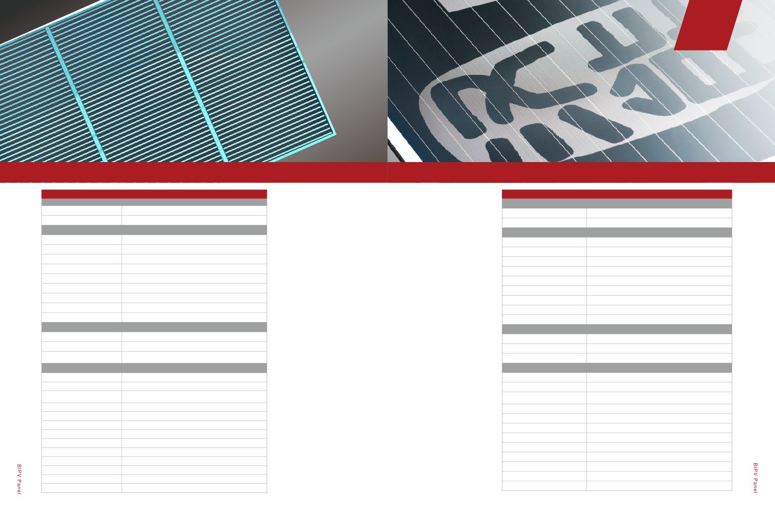
1.3.2 Carved translucent Panel
1.3.3 Colored translucent Panel
1.3.4 Hollow Panel
1.3.5 Double-sided power Panel
1.3.6 Allotype Panel
1.3.7 Splice Panel
1.3.8 LOGO Panel
Chapter 01
PRODUCT
PRESENTATION
1.1
Standard Panel
Key product features:
Advanced technology, excellent quality, positive tolerance panels,
assurance for more generating capacity
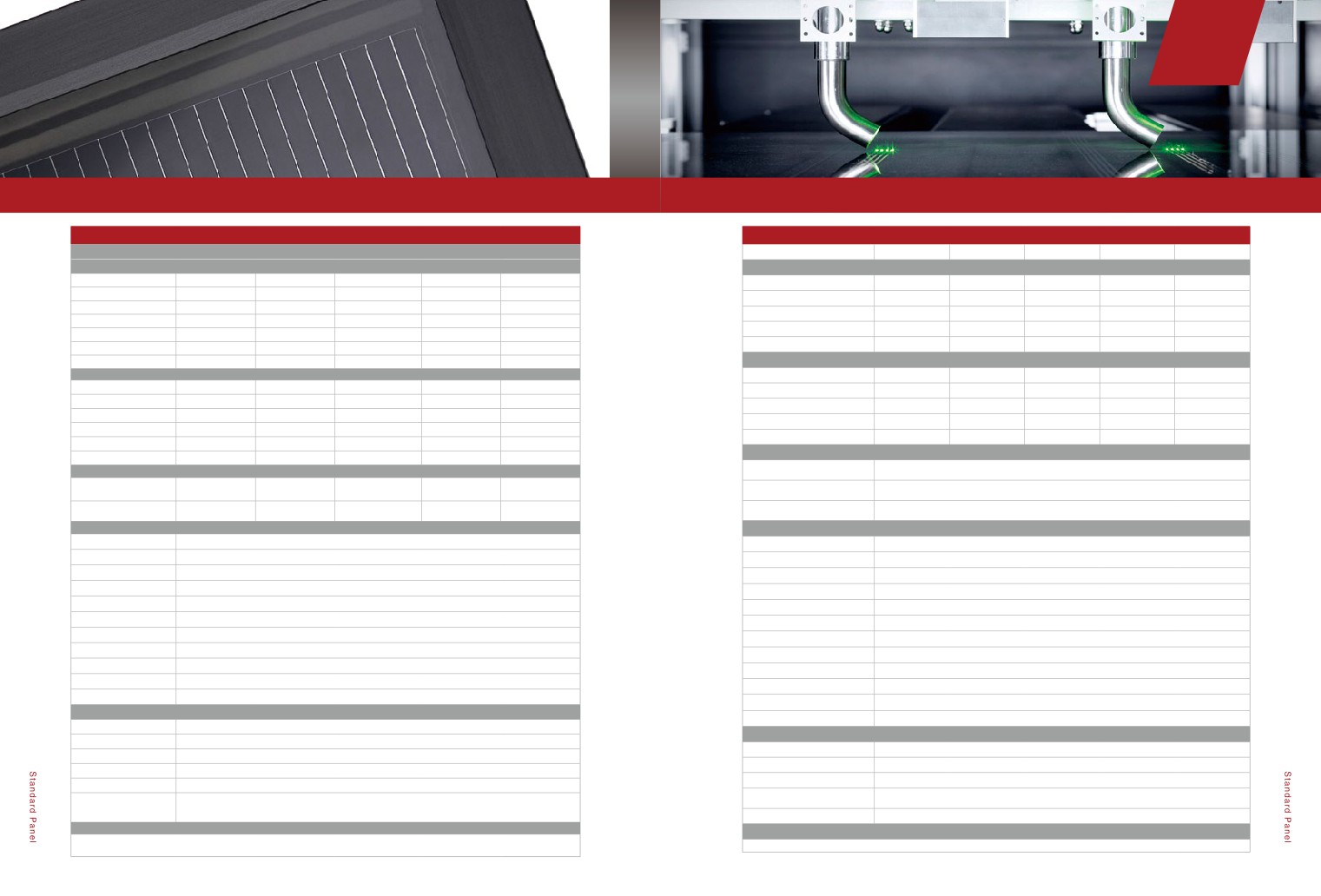
1.1.1
MiaSoé CIGS Panel
1.1.2
Solibro SL2 CIGS Panel
MiaSoé MS SERIES -04
SOLIBRO SL2
ELECTRICAL PERFORMANCE
ELECTRICAL PERFORMANCE
Standard Test Conditions (STC) :1000 W/m2 ,25℃ cell temperature,AM 1.5 G spectrum
Standard Test Conditions (STC) :1000 W/m2 ,25℃ cell temperature,AM 1.5 G spectrum
Power Class (W)
100
105
110
115
120
Minimum Power(+5/-0W)
100.0
105.0
110.0
115.0
120.0
MS150GG-04
MS155GG-04
MS160GG-04
MS165GG-04
MS170GG-04
MS175GG-04
Short Circuit Current (A)
1.68
1.68
1.69
1.69
1.69
Nominal Power (W)
150
155
160
165
170
175
Open Circuit voltage (V)
90.1
91.6
93.3
95.1
97.6
Current at PMPP (A)
1.46
1.49
1.52
1.54
1.56
Nomical Efficiency (% )
14.0%
14.5%
14.9%
15.4%
15.9%
16.3%
Voltage at PMPP (V)
68.5
70.5
72.4
74.7
76.9
Nominal efficiency (%)
≥ 10.6
≥ 11.2
≥ 11.7
≥ 12.2
≥ 12.8
Power Output Tolerance (W)
+5/-0
+5/-0
+5/-0
+5/-0
+5/-0
+5/-0
PERFORMANCE AT NORMAL OPERATING CELL TEMPERATURE(800W/m2 51±2℃,AM 1.5 G SPECTRUM)
Maximum Power Voltage (V)
19.2
19.6
19.9
20.3
20.7
21.0
Power Class (W)
100
105
110
115
120
Minimum Power(+5/-0W)
72.3
75.9
79.5
83.1
86.7
Maximum Power Current (A)
7.82
7.92
8.02
8.13
8.23
8.33
Short Circuit Current (A)
1.34
1.34
1.35
1.35
1.35
Output Circuit Voltage (V)
24.4
24.7
24.9
25.2
25.5
25.8
Open Circuit voltage (V)
82.0
83.4
84.9
86.5
88.8
Current at PMPP (A)
1.16
1.18
1.21
1.22
1.24
Short Circuit Current (A)
9.08
9.09
9.10
9.12
9.13
9.15
Voltage at PMPP (V)
62.1
64.0
65.7
67.8
69.8
TEMPERATURE COEFFICIENTS (AT 1000W/m2 ,AM 1.5 G SPECTRUM)
Maximum Series Fuse Rating (A)
25
Temperature Coefficient of ISC
Temperature Coefficient
α
±0.04
β
-0.29±0.04
(%K)
of VOC (%K)
Maximum System Voltage (V)
1000 / 1000
Temperature Coefficient of
γ
-0.38±0.04
PMPP (%K)
TEMPERATURE COEFFICIENTS
MECHANICAL SPECIFICATION
NOCT
45
Length
1190(+3/-1)mm
Width
789.5(+3/-1)mm
Temperature Coefficient of
-0.40
Pmpp (% / ℃ )
Height
7.3mm(+Junction box, 15mm)
Temperature Coefficient of Voc
Weight
16.5KG
-0.35
(% / ℃ )
Front cover
4 mm tempered low iron glass (ESG)
Temperature Coefficient of Isc
-0.003
(% / ℃ )
Back cover
3 mm float glass
Frame
None
MECHANICAL SPECIFICATION
Cell type
CIGS [Cu(In, Ga) Se2]
Length(mm)
1611
Junction box
Protection class IP 65, with 1 bypass diode (3A);66x54x15mm3
Width(mm)
665
Cable type
2.5mm2 Solar cable;(+)855(+30/-0)mm;(-)735(+30/-0)mm
Connector
MC4
Depth(mm)
7.5 / 28(including junction box)
PROPERTIES FOR SYSTEM DESIGN
Weight(kg)
18
Maximum System voltage (V)
1000 (IEC) / 600 (UL 1703)
Junction Box /Output Terminal
Maximum Reverse Curren (A)
5
2 corner connection boxes / MC4 type
Type
Wind / Snow Load (Pa)
2400
Maximum Load
Tested snow load: 5400N / m2
Safety Class
II
QUALIFICATIONS AND CERTIFICATES
Fire Rating
C
5 years warranty for materials and process;
Permitted module temperature
-40℃ bis +85℃
10 years 90%/25 years 80% warranty for power output
on continous duty
QUALIFICATIONS AND CERTIFICATES
IEC 61646, IEC 61730 (Application Class A), UL 1703 (Fire Class A)
EC 61646 (Ed. 2), IEC 61730 (Ed.1) application class A, UL 1703
The production site is certified according to ISO 9001 for Quality Management.
2
3
Chapter 01
PRODUCT
PRESENTATION
Key product features:
Key product features:
Stable and reliable quality, low-voltage, easy system design;
Simple installation, especially for small rooftop systems.
Safe and environmental-friendly.
1.1.3
Solibro SL2-F CIGS Panel
1.1.4
a-Si/uc-Si Panel
SOLIBRO SL2-F
a-Si/uc-Si Panel
ELECTRICAL PERFORMANCE
Panel Type
HNS-SD120
HNS-SD125
HNS-SD130
HNS-SD135
HNS-SD140
Standard Test Conditions (STC) :1000 W/m2 ,25℃ cell temperature,AM 1.5 G spectrum
ELECTRICAL PERFORMANCE(STC:1000W/m2,25℃,AM1.5)
Power Class (W)
100
105
110
115
120
Nominal Power (W)
120
125
130
135
140
Minimum Power(+5/-0W)
100.0
105.0
110.0
115.0
120.0
Maximum Power Voltage (V)
49
51
54
56
59
Short Circuit Current (A)
1.68
1.68
1.69
1.69
1.69
Maximum Power Current (A)
2.27
2.26
2.22
2.19
2.17
Open Circuit voltage (V)
90.1
91.6
93.3
95.1
97.6
Output Circuit Voltage (V)
67
69
71
73
75
Current at PMPP (A)
1.46
1.49
1.52
1.54
1.56
Short Circuit Current (A)
2.74
2.72
2.65
2.62
2.58
Voltage at PMPP (V)
68.5
70.5
72.4
74.7
76.9
Nominal efficiency (%)
≥ 10.5
≥ 11.0
≥ 11.6
≥ 12.1
≥ 12.6
ELECTRICAL CHARACTERISTICS(NOCT:800W/m2,45℃,AM1.5)
Performance At Normal Operating Cell Temperature(800W/m2 51±2℃,AM 1.5 G spectrum)
Nominal Power (W)
90
94
97
101
105
Power Class (W)
100
105
110
115
120
Maximum Power Voltage (V)
61
62
64
66
67
Minimum Power(+5/-0W)
72.3
75.9
79.5
83.1
86.7
Maximum Power Current (A)
2.26
2.25
2.19
2.17
2.14
Short Circuit Current (A)
1.34
1.34
1.35
1.35
1.35
Output Circuit Voltage (V)
44
46
48
50
53
Open Circuit voltage (V)
82.0
83.4
84.9
86.5
88.8
Short Circuit Current (A)
1.91
1.90
1.86
1.84
1.82
Current at PMPP (A)
1.16
1.18
1.21
1.22
1.24
TEMPERATURE COEFFICIENTS
Voltage at PMPP (V)
62.1
64.0
65.7
67.8
69.8
Temperature Coefficient of Pmpp (%
Temperature Coefficients (AT 1000W/m2
,AM 1.5 G spectrum)
-0.29
/ ℃ )
Temperature Coefficient of
Temperature Coefficient
Temperature Coefficient of Voc (% /
α
±0.04
β
-0.29±0.04
-0.32
ISC (%K)
of VOC (%K)
℃)
Temperature Coefficient of
Temperature Coefficient of Isc (% /
γ
-0.38±0.04
+0.07
PMPP (%K)
℃)
MECHANICAL SPECIFICATION
MECHANICAL SPECIFICATION
Length
1196.6(+1/-0.2)mm
Front cover
Low Iron Float Glass,3.2mm
Width
796.1(+1/-0.2)mm
Back cover
Tempered glass,3.2mm
Height
30mm
Materials
White EVA
Weight
18.1KG
Cell type
Tandem (a-Si/µc-Si)
Front cover
4 mm tempered low iron glass (ESG)
Junction Box Class
IP67
Back cover
3 mm float glass
Length (mm)
1300
Frame
Aluminum frame, black
Width (mm)
1100
Cell type
CIGS [Cu(In, Ga) Se2]
Depth (mm)
6.8 (Junction Box not included)
Junction box
Protection class IP 65, with 1 bypass diode (3A);66x54x15mm3
Area (m2)
1.43
Cable type
2.5mm2 Solar cable;(+)855(+30/-0)mm;(-)735(+30/-0)mm
Weight (Kg)
25
Connector
MC4
Cable Length (mm)
(+875) / (-565)
PROPERTIES FOR SYSTEM DESIGN
Connector
MC4 Compatible
Maximum System voltage (V)
1000 (IEC) / 600 (UL 1703)
PROPERTIES FOR SYSTEM DESIGN
Maximum Reverse Curren (A)
5
Maximum System voltage
1000V
Wind / Snow Load (Pa)
2400
Maximum Series Fuse Rating
6A
Safety Class
II
Power Output Tolerance
0/+5W
Fire Rating
C
Permitted module temperature on
Permitted module
-40℃ bis +85℃
continous duty
temperature on continous
-40℃ bis +85℃
duty
Load
2400Pa
QUALIFICATIONS AND CERTIFICATES
QUALIFICATIONS AND CERTIFICATES
EC 61646 (Ed. 2), IEC 61730 (Ed.1) application class A, UL 1703
CE、TUV Rheinland
The production site is certified according to ISO 9001 for Quality Management.
4
5
Chapter 01
PRODUCT
1.2
Flexible/Light weight Panel
PRESENTATION
MiaSolé FLEX SERIES
Key product features:
Lightweight, super thin, flexible, especially
suitable for light loads and curved roof;
Key product features:
Safe and reliable, can be directly attached,
High-temperature adaptability, good low-light
low installation costs;
generation performance.
Two widths panel options to choose from.
1.1.5
a-Si/Ge Panel
1.2.1
MiaSolé FLEX CIGS Panel
HNS-BT65B
MiaSoé FLEX-01W
PERFORMANCE
ELECTRICAL PERFORMANCE
Substrate
TCO Glass
FLEX-01 200W
FLEX-01 210W
FLEX-01 220W
FLEX-01 230W
PIN/PIN/PIN Triple-junction a-Si/Ge Cell, Glass-glass/J-box at back side non
Panel Type
Nominal Power(W)
200
210
220
230
see-through module
ELECTRICAL PERFORMANCE
Power Output Tolerance(W)
+10/-0
+10/-0
+10/-0
+10/-0
Maximum Power(W)
65
Maximum Power Voltage(V)
21.7
22.2
22.6
23.1
Maximum Power Voltage (V)
70
Maximum Power Current(A)
9.52
9.73
9.86
10.03
Maximum Power Current (A)
0.93
Open Circuit Voltage(V)
27.6
27.8
28.2
28.6
Output Circuit Voltage (V)
89
Short Circuit Current(A)
11.10
11.10
11.13
11.29
Short Circuit Current (A)
1.12
Module aperture area efficiency(%)
13.9%
14.6%
15.3%
16.0%
Power Output Tolerance(W)
0/+3
Maximum System Voltage(V)
1000 / 600
Maximum System voltage(V)
1000
Maximum Series Fuse Rating(A)
20
Maximum Series Fuse Rating(A)
2
TEMPERATURE COEFFICIENTS
TEMPERATURE COEFFICIENTS
Temperature Coefficient of Pmpp ( /
-0.45
Temperature Coefficient of Isc ( / ℃ )
0.02%
℃)
Temperature Coefficient of Voc ( / ℃ )
-0.20%
Temperature Coefficient of Voc ( / ℃ )
-0.36
Temperature Coefficient of Pmpp ( / ℃ )
-0.19%
Temperature Coefficient of Isc ( / ℃ )
-0.003
MECHANICAL SPECIFICATION
MECHANICAL SPECIFICATION
Length(mm)
1245
Length(mm)
1710
Width(mm)
635
Width(mm)
999
Height(mm,Junction Box not included)
9.7
Thickness(mm,Maximum at J-Box)
17
Weight(kg)
18.6
Weight (Module without adhesive)
4.2
(kg)
Area(m2)
0.79
Weight / Area(kg/m2)(Module
2.47
Junction box Type
Back connecting boxes
without adhesive)
Junction Box Class
IP68
Thickness of Junction Box(mm)
20
Junction Box Class
IP67
Cable Connections
MC4 Compatible
Cable Length(mm)
450
Cell Type
CIGS
Materials
PVB
QUALIFICATIONS AND CERTIFICATES
Front cover
3.2mm TCO
5 year workmanship; 5/10/25 year power output
Back cover
6.0mm Semi-tempered/ Tempered glass
UL1703,IEC61646,IEC61730(Application Class A)
6
7
第
章
01
产品介绍
Global Solar Power FLEX Series
Key product features:
Lightweight, super thin, flexible, especially suitable
for light loads and curved roofs;
Safe and reliable, can be directly attached, low
installation costs;
Three lengths panel options to choose from.
1.2.2
Global Solar PowerFLEX™ CIGS Panel
MiaSoé FLEX-01N
Global Solar PowerFLEX™(90/100W)
ELECTRICAL PERFORMANCE
ELECTRICAL PERFORMANCE
Capacity rating
Pmax
100W
90W
FLEX-01 60N
FLEX-01 65N
FLEX-01 70N
FLEX-01 75N
Tolerance of Pmax
%
+/-5%
+/-5%
Nominal Power(W)
60
65
70
75
Module aperture area
%
12.7%
11.4%
efficiency
Power Output Tolerance (W)
+5/-0
+5/-0
+5/-0
+5/-0
Rated voltage
Vmpp
17.8V
16.5V
Rated current
Impp
5.6A
5.4A
Maximum Power Voltage(V)
21.6
21.7
22.3
22.8
Open circuit voltage
Voc
23.3V
22.0V
Maximum Power Current(A)
2.93
3.17
3.25
3.32
Short circuit current
Isc
6.4A
6.3A
Open Circuit Voltage(V)
27.1
27.6
27.9
28.3
Note 1: Standard Test Conditions (STC): Cell Temperature at 25° C; Solar irradiance intensity of 1000 W/m2; AM1.5 solar reference spectrum
(ASTM E892)
Note 2: Average efficiency is calculated using the 0.79 m2 aperture area of the module
Short Circuit Current(A)
3.62
3.70
3.70
3.73
Note 3: Electrical parameters are +/-10% unless stated otherwise
Module aperture area efficiency (%)
12.5%
13.5%
14.6%
15.6%
TEMPERATURE COEFFICIENTS
Low-Light Performance
Maximum power(Pmax)
-0.43% / ℃

Intensity(W/m2 )
Maximum System Voltage(V)
1000 / 600
Maximum voltage(Vmax)
-0.38% / ℃
1000
Maximum Series Fuse Rating(A)
10
Open circuit voltage(Voc)
-0.33% / ℃
500
Short circuit current(Isc)
-0.03% / ℃
200
TEMPERATURE COEFFICIENTS
Note: Relative to Standard Test Conditions
Note: Relative to Standard Test Conditions (STC): Solar irradiance intensity of 1000 W/m2; AM1.5
(STC): Cell Temperature at 25°C; AM1.5
Temperature Coefficient of Pmpp ( / ℃ )
-0.45
solar reference spectrum (ASTM E892)
solar reference spectrum (ASTM E892)
Temperature Coefficient of Voc ( / ℃ )
-0.36
MECHANICAL SPECIFICATIONS
Length
2017mm
Temperature Coefficient of Isc ( / ℃ )
-0.003
Width
494mm
MECHANICAL SPECIFICATION
Thickness
3mm
Weight(without adhesive)
2.6kg(2.6kg/m2)±5%
Length(mm)
1710
Weight(with adhesive)
3.3kg(3.3kg/m2)±5%
Width(mm)
370
Junction Box - Top Mounted
Micro Junction Box
Cables
4 mm2 dual rated with SOLARLOKTM connectors
Thickness(mm,Maximum at J-Box)
17
Junction Box - Bottom
MC-JM/FM (MC4 Connectors)
Mounted
Weight (Module without adhesive)(kg)
1.7
Front Sheet
Non-stick ETFE(F-40)
Weight / Area(kg/m2)(Module without
2.69
Solar Cells
36 CIGS cells (210 x 100 mm)
adhesive)
Adhesive
ADCO HelioBondTM PVA 600BT butyl mastic
Junction Box Type
IP68
Hot Spot Protection
Bypass diodes at each cell; 1 at junction box
Cable Connections
MC4 Compatible
Materials
Lead free and exempt from RoHS requirements
Maximum Series Fuse Rating
10 Amp
Cell Type
CIGS
Color Options
Black (B) or White (W) backsheet behind cells
QUALIFICATIONS AND CERTIFICATES
OPERATING CONDITIONS
5 year workmanship; 5/10/25 year power output
Temperature Range
-40° C to + 85° C
Maximum System Voltage
1000VDC IEC, 600VDC UL
UL1703,IEC61646,IEC61730(Application Class A)
QUALIFICATIONS AND CERTIFICATES
EN61646,EN61730,UL1703

Materials and workmanship - 5 years;Power output - 25 years (90% @ 10 yrs; 80% @ 25 yrs) Limited Warranty
8
9
Chapter 01
PRODUCT
PRESENTATION
Global Solar PowerFLEX™ (185/200W)
Global Solar PowerFLEX™(275/300W)
ELECTRICAL PERFORMANCE
ELECTRICAL PERFORMANCE
Capacity rating
Pmax
200W
185W
Capacity rating
Pmax
300W
275W
Tolerance of Pmax
%
+/-5%
+/-5%
Tolerance of Pmax
%
+/-5%
+/-5%
Module aperture area
Module aperture area
%
12.6%
11.7%
%
12.6%
11.5%
efficiency
efficiency
Rated voltage
Vmpp
36.2V
34.7V
Rated voltage
Vmpp
54.3V
51.5V
Rated current
Impp
5.5A
5.3A
Rated current
Impp
5.5A
5.3A
Open circuit voltage
Voc
46.4V
45.6V
Open circuit voltage
Voc
69.7V
67.6V
Short circuit current
Isc
6.4A
6.3A
Short circuit current
Isc
6.4A
6.3A
Note 1: Standard Test Conditions (STC): Cell Temperature at 25° C; Solar irradiance intensity of 1000 W/m2; AM1.5 solar reference spectrum
Note 1: Standard Test Conditions (STC): Cell Temperature at 25° C; Solar irradiance intensity of 1000 W/m2; AM1.5 solar reference spectrum
(ASTM E892)
(ASTM E892)
Note 2: Average efficiency is calculated using the 1.59 m2 aperture area of the module
Note 2: Average efficiency is calculated using the 2.38 m2 aperture area of the module
Note 3: Electrical parameters are +/-10% unless stated otherwise
Note 3: Electrical parameters are +/-10% unless stated otherwise
TEMPERATURE COEFFICIENTS
Low-Light Performance
TEMPERATURE COEFFICIENTS
Low-Light Performance
Maximum power(Pmax)
-0.43% / ℃

Intensity(W/m2 )
Maximum power(Pmax)
-0.43% / ℃

Intensity(W/m2 )
Maximum voltage(Vmax)
-0.38% / ℃
1000
Maximum voltage(Vmax)
-0.38% / ℃
1000
Open circuit voltage(Voc)
-0.33% / ℃
500
Open circuit voltage(Voc)
-0.33% / ℃
500
Short circuit current(Isc)
-0.03% / ℃
200
Short circuit current(Isc)
-0.03% / ℃
200
Note: Relative to Standard Test Conditions
Note: Relative to Standard Test Conditions
Note: Relative to Standard Test Conditions (STC): Solar irradiance intensity of 1000 W/m2; AM1.5
Note: Relative to Standard Test Conditions (STC): Solar irradiance intensity of 1000 W/m2; AM1.5
(STC): Cell Temperature at 25°C; AM1.5
(STC): Cell Temperature at 25°C; AM1.5
solar reference spectrum (ASTM E892)
solar reference spectrum (ASTM E892)
solar reference spectrum (ASTM E892)
solar reference spectrum (ASTM E892)
MECHANICAL SPECIFICATIONS
MECHANICAL SPECIFICATIONS
Length
3881mm
Length
5745mm
Width
494mm
Width
494mm
Thickness
3mm
Thickness
3mm
Weight(without adhesive)
4.9kg(2.6kg/m2)±5%
Weight(without adhesive)
7.2kg(2.6kg/m2)±5%
Weight(with adhesive)
6.3kg(3.3kg/m2)±5%
Weight(with adhesive)
9.3kg(3.3kg/m2)±5%
Junction Box - Top Mounted
Micro Junction Box
Junction Box - Top Mounted
Micro Junction Box
Cables
4 mm2
dual rated with SOLARLOKTM connectors
Cables
4 mm2 dual rated with SOLARLOKTM connectors
Junction Box - Bottom
Junction Box - Bottom
MC-JM/FM (MC4 Connectors)
MC-JM/FM (MC4 Connectors)
Mounted
Mounted
Front Sheet
Non-stick ETFE(F-40)
Front Sheet
Non-stick ETFE(F-40)
Solar Cells
72 CIGS cells (210 x 100 mm)
Solar Cells
108 CIGS cells (210 x 100 mm)
Adhesive
ADCO HelioBondTM PVA 600BT butyl mastic
Adhesive
ADCO HelioBondTM PVA 600BT butyl mastic
Hot Spot Protection
Bypass diodes at each cell; 1 at junction box
Hot Spot Protection
Bypass diodes at each cell; 1 at junction box
Materials
Lead free and exempt from RoHS requirements
Materials
Lead free and exempt from RoHS requirements
Maximum Series Fuse Rating
10 Amp
Maximum Series Fuse Rating
10 Amp
Color Options
Black (B) or White (W) backsheet behind cells
Color Options
Black (B) or White (W) backsheet behind cells
OPERATING CONDITIONS
OPERATING CONDITIONS
Temperature Range
-40° C to + 85° C
Temperature Range
-40° C to + 85° C
Maximum System Voltage
1000VDC IEC, 600VDC UL
Maximum System Voltage
1000VDC IEC, 600VDC UL
QUALIFICATIONS AND CERTIFICATES
QUALIFICATIONS AND CERTIFICATES
EN61646,EN61730,UL1703
EN61646,EN61730,UL1703

Materials and workmanship - 5 years;Power output - 25 years (90% @ 10 yrs; 80% @ 25 yrs) Limited Warranty

Materials and workmanship - 5 years;Power output - 25 years (90% @ 10 yrs; 80% @ 25 yrs) Limited Warranty
10
11
Chapter 01
PRODUCT
PRESENTATION
Key product features:
PET sheet substrate, light weight per unit area;
Good low-light effect, low temperature coefficient,
various colors.
1.2.3
Light weight Panel
HNS-BT65QA
HNS-BT65QB
CHARACTERISTIC
CHARACTERISTIC
Panel Type
PIN/PIN/PIN Triple-junction a-Si/Ge Cell
Panel Type
PIN/PIN/PIN Triple-junction a-Si/Ge Cell
ELECTRICAL PERFORMANCE
ELECTRICAL PERFORMANCE
Maximum power(V)
70
Maximum power(V)
70
Maximum voltage(A)
0.93
Maximum voltage(A)
0.93
Output Circuit Voltage (V)
89
Output Circuit Voltage (V)
89
Short Circuit Current (A)
1.12
Short Circuit Current (A)
1.12
Power Output Tolerance(W)
0/+3
Power Output Tolerance(W)
0/+3
Maximum System voltage(V)
1000
Maximum System voltage(V)
1000
Maximum Series Fuse Rating(A)
2
Maximum Series Fuse Rating(A)
2
TEMPERATURE COEFFICIENTS
TEMPERATURE COEFFICIENTS
Temperature Coefficient of Isc ( / ℃ )
0.02%
Temperature Coefficient of Isc ( / ℃ )
0.02%
Temperature Coefficient of Voc ( / ℃ )
-0.20%
Temperature Coefficient of Voc ( / ℃ )
-0.20%
Temperature Coefficient of Pmpp ( / ℃ )
-0.19%
Temperature Coefficient of Pmpp ( / ℃ )
-0.19%
MECHANICAL SPECIFICATION
MECHANICAL SPECIFICATION
Length(mm)
1245
Length(mm)
1245
Width(mm)
635
Width(mm)
635
Height(mm,Junction Box not included)
4.0
Height(mm,Junction Box not included)
4.8
Weight (kg)
8.9
Weight (kg)
9.0
Area(m2)
0.79
Area(m2)
0.79
Junction box Type
Back connecting boxes
Junction box Type
Back connecting boxes
Thickness of Junction Box(mm)
20
Thickness of Junction Box(mm)
20
Junction Box Class
IP67
Junction Box Class
IP67
Cable Length(mm)
450
Cable Length(mm)
450
Materials
EVA
Materials
EVA
Front cover
3.2mm TCO
Front cover
2.5mm TCO
Back cover
0.37mm PET
Back cover
2.0 Tempered glass
12
13
Chapter 01
PRODUCT
1.3
BIPV Panel
PRESENTATION
Key product features:
Key product features:
Translucent uniform penetration of different
5% to 30% transmittance options, various
spectral selectivity, good low-light effect, can
scribing linewidth options, can be widely
be widely used in agriculture greenhouse.
applied to walls, skylights, etc.
1.3.1
Back electrode translucent Panel
HNS-BS30/BD40/BT55TB
HNS-BT51TK
CHARACTERISTIC
CHARACTERISTIC
PIN a-Si/Ge Cell, Glass-glass/Side J-box /see-through
PIN/PIN/PIN Triple-junction a-Si/Ge Cell,Glass-glass/Side J-box /
Panel Type
Panel Type
module
see-through module
ELECTRICAL PERFORMANCE
ELECTRICAL PERFORMANCE
Transmittance
40%
20%
10%
Transmittance
20%
Laser etching liner width
Maximum Power(W)
30
40
55
0.3
0.67
1
3
(mm)
Maximum Power Voltage (V)
20
46
67
Maximum Power(W)
45
51
51
51
Maximum Power Current (A)
1.5
0.87
0.82
Maximum Power Voltage (V)
64
69
69
69
Output Circuit Voltage (V)
31
58
84
Maximum Power Current (A)
0.71
0.74
0.74
0.74
Short Circuit Current (A)
2
1.08
0.99
Output Circuit Voltage (V)
84
89
89
89
Power Output Tolerance(W)
±1
±1.5
±2
Short Circuit Current (A)
0.89
0.89
0.89
0.89
Maximum System voltage(V)
1000
Power Output Tolerance(W)
0 / +2
Maximum System voltage
Maximum Series Fuse Rating(A)
3
1000
(V)
TEMPERATURE COEFFICIENTS
Maximum Series Fuse Rating
2
(A)
Temperature Coefficient of Isc ( /
0.02%
℃)
TEMPERATURE COEFFICIENTS
Temperature Coefficient of Voc (
Temperature Coefficient of
-0.20%
0.02%
/ ℃ )
Isc ( / ℃ )
Temperature Coefficient of Pmpp
Temperature Coefficient of
-0.19%
-0.20%
( / ℃ )
Voc ( / ℃ )
MECHANICAL SPECIFICATION
Temperature Coefficient of
-0.19%
Pmpp ( / ℃ )
Length(mm)
1245
MECHANICAL SPECIFICATION
Width(mm)
635
Length(mm)
1245
Height(mm,Junction Box not
9.7
Width(mm)
635
included)
Weight (kg)
18.6
Height(mm,Junction Box
9.7
not included)
Area(m2)
0.79
Weight (kg)
18.6
Junction box Type
Side Junction box
Area(m2)
0.79
Thickness of Junction Bo(mm)
12.6
Junction box Type
Side Junction box
Junction Box Class
IP67
Thickness of Junction Box
12.6
(mm)
Cable Length(mm)
450
Junction Box Class
IP67
Materials
PVB
Cable Length(mm)
450
Front cover
3.2mm TCO
Materials
PVB
Back cover
6.0mm Semi-tempered/ Tempered glass
Front cover
3.2mm TCO
Back cover
6.0mm Semi-tempered/ Tempered glass
14
15
Chapter 01
PRODUCT
PRESENTATION
Key product features:
Key product features:
Various colors, applicable to all types of
Hollow panel, meeting the energy
architectural curtain walls that have color
efficiency requirement of buildings.
requirements.
1.3.3
Colored translucent Panel
1.3.4
Hollow Panel
HNS-BT50C
HNS-BT45Z
CHARACTERISTIC
CHARACTERISTIC
Substrate
TCO Glass
Substrate
TCO Glass
PIN/PIN/PIN Triple-junction a-Si/Ge Cell,Glass-glass/Side J-box /
Triple-junction a-Si/Ge Cell,Glass-glass/Side J-box /see-through /
Panel Type
Panel Type
Colorful/ see-through module
Insulating module
ELECTRICAL PERFORMANCE
ELECTRICAL PERFORMANCE
Color
Blue / Green / Yellow / Orange
Transmittance
20%
Transmittance
20%
Maximum Power(W)
45
Silicone
Maximum Power(W)
51
Maximum Power Voltage (V)
64
Maximum Power Voltage (V)
69
Maximum Power Current (A)
0.71
Maximum Power Current (A)
0.74
Output Circuit Voltage (V)
84
Output Circuit Voltage (V)
88
Short Circuit Current (A)
0.89
Short Circuit Current (A)
0.89
Power Output Tolerance(W)
0/+2
Power Output Tolerance(W)
0/+2
Maximum System voltage
1000
(V)
Maximum System voltage
1000
Maximum Series Fuse Rating
(V)
2
(A)
Maximum Series Fuse Rating
2
(A)
TEMPERATURE COEFFICIENTS
TEMPERATURE COEFFICIENTS
Front 3.2mm TCO glass
Temperature Coefficient of
0.02%
Isc ( / ℃ )
Temperature Coefficient of
Back Tempered glass
0.02%
Temperature Coefficient of
Isc ( / ℃ )
-0.20%
Desiccant
Voc ( / ℃ )
Temperature Coefficient of
-0.20%
Tempered glass
Temperature Coefficient of
Voc ( / ℃ )
-0.19%
Pmpp ( / ℃ )
Temperature Coefficient of
-0.19%
Pmpp ( / ℃ )
MECHANICAL SPECIFICATION
MECHANICAL SPECIFICATION
Length(mm)
Customized
Length(mm)
1245
Width(mm)
Width(mm)
635
Height(mm,Junction Box
27.7
not included)
Height(mm,Junction Box
9.7
Weight (kg)
30.4
not included)
Weight (kg)
18.6
Area(m2)
0.79
Area(m2)
0.79
Junction box Type
Side Junction box
Junction box Type
Side Junction box
Thickness of Junction Box
12.6
(mm)
Thickness of Junction Box
12.6
Junction Box Class
IP67
(mm)
Junction Box Class
IP67
Cable Length(mm)
450
Cable Length(mm)
450
Materials
PVB
Materials
PVB
Front cover
3.2mm TCO
Front cover
3.2mm TCO
Back cover
6.0mm Semi-tempered/ Tempered glass
16
Back cover
6.0mm Semi-tempered/ Tempered glass
Insulating glass
6.0mm Tempered glass
17
Chapter 01
PRODUCT
PRESENTATION
Key product features:
Key product features:
Double-sided power, high overall power
Diverse modeling, can be tailor-made
generation efficiency, can be widely used
to fit the architectural design of the
for sound barrier or noise screens.
building.
1.3.5
Double-sided power Panel
1.3.6
Allotype Panel
HNS-BT123S
CHARACTERISTIC
Substrate
TCO Glass
HNS-BT15Y
PIN/PIN/PIN Triple-junction a-Si/Ge Cell,PIN/PIN a-Si/Ge tandem
CHARACTERISTIC
Panel Type
Cell,Triple Glazing/ Double Side Junction Box
Substrate
TCO Glass
ELECTRICAL PERFORMANCE
PIN/PIN/PIN Triple-junction a-Si/Ge Cell,Glass-glass/Side J-box /
Panel Type
Maximum Power(W)
65
58
see-through module
Maximum Power Voltage (V)
70
43
ELECTRICAL PERFORMANCE
Maximum Power Current (A)
0.93
1.36
Transmittance
20%
Output Circuit Voltage (V)
89
58.5
Maximum Power(W)
15
Short Circuit Current (A)
1.12
1.56
Maximum Power Voltage (V)
60
Power Output Tolerance(W)
0/+3
±1
Maximum Power Current (A)
0.25
Maximum System voltage
Output Circuit Voltage (V)
80
1000
(V)
Maximum Series Fuse Rating
Short Circuit Current (A)
0.3
5
(A)
Power Output Tolerance(W)
0/+1
TEMPERATURE COEFFICIENTS
Maximum System voltage
Temperature Coefficient of
1000
0.02%
(V)
Isc ( / ℃ )
Maximum Series Fuse Rating
Temperature Coefficient of
2
-0.20%
(A)
Voc ( / ℃ )
TEMPERATURE COEFFICIENTS
Temperature Coefficient of
-0.19%
Pmpp ( / ℃ )
Temperature Coefficient of
0.02%
Isc ( / ℃ )
MECHANICAL SPECIFICATION
Temperature Coefficient of
-0.20%
Length(mm)
1245
Voc ( / ℃ )
Temperature Coefficient of
Width(mm)
635
-0.19%
Pmpp ( / ℃ )
Height(mm,Junction Box
8
MECHANICAL SPECIFICATION
not included)
Weight (kg)
15.8
Length(mm)
Area(m2)
0.79
Weight (kg)
Customized
Junction Box Type
Side Junction box
Area(m2)
Thickness of Junction Box
12.6
Height(mm,Junction Box
(mm)
7.5
not included)
Junction Box Class
IP67
Junction box Type
Side Junction box
Cable Length(mm)
450
Thickness of Junction Box
12.6
Materials
EVA
(mm)
Front cover
2.5mm TCO
Junction Box Class
IP67
Intermediate glass
2.0mm Non-Tempered glass
Cable Length(mm)
450
Back cover
2.5mm TCO
Materials
PVB
18
Front cover
3.2mm TCO
19
Back cover
4.0mm Semi-tempered/ Tempered glass
Chapter 01
PRODUCT
PRESENTATION
Key product features:
Key product features:
Three layers of plastic sheets with multiple
Integration of corporate logo with solar
cell chips pulled and spliced, can meet the
panels to achieve a win-win solution for
requirement of large size curtain walls.
power generation and corporate branding.
1.3.7
Splice Panel
1.3.8
LOGO Panel
HNS-BT153TP
HNL-1
CHARACTERISTIC
CHARACTERISTIC
Substrate
TCO Glass
Substrate
TCO Glass
Panel Type
PIN/PIN/PIN Triple-junction a-Si/Ge Cell
Panel Type
PIN/PIN/PIN Triple-junction a-Si/Ge Cell
ELECTRICAL PERFORMANCE
ELECTRICAL PERFORMANCE
Transmittance
20%
Transmittance
40%
Maximum Power(W)
153
Maximum Power(W)
32
Maximum Power Voltage (V)
62
Maximum Power Voltage (V)
63
Maximum Power Current (A)
2.48
Maximum Power Current (A)
0.51
Output Circuit Voltage (V)
82
Output Circuit Voltage (V)
84
Short Circuit Current (A)
3.28
Short Circuit Current (A)
0.67
Power Output Tolerance(W)
0/+5
Power Output Tolerance(W)
0/+3
Maximum System voltage(V)
1000
Maximum System voltage(V)
1000
Maximum Series Fuse Rating(A)
5
Maximum Series Fuse Rating(A)
2
TEMPERATURE COEFFICIENTS
TEMPERATURE COEFFICIENTS
Temperature Coefficient of Isc ( / ℃ )
0.02%
Temperature Coefficient of Isc ( / ℃ )
0.02%
Temperature Coefficient of Voc ( / ℃ )
-0.20%
Temperature Coefficient of Voc ( / ℃ )
-0.20%
Temperature Coefficient of Pmpp ( /
-0.19%
Temperature Coefficient of Pmpp ( / ℃ )
-0.19%
℃)
MECHANICAL SPECIFICATION
MECHANICAL SPECIFICATION
Length(mm)
2540
Length(mm)
1245
Width(mm)
1245
Width(mm)
635
Height(mm,Junction Box not
Height(mm,Junction Box not
16.2
9.7
included)
included)
Weight (kg)
124
Weight (kg)
18.6
Area(m2)
3.16
Area(m2)
0.79
Junction Box Type
Side Junction box
Junction box Type
Back connecting boxes
Thickness of Junction Box(mm)
12.6
Thickness of Junction Box(mm)
20
Junction Box Class
IP67
Junction Box Class
IP67
Cable Length(mm)
1800
Cable Length(mm)
450
Materials
PVB
Materials
EVA/PVB
Front cover
6.0mm Semi-tempered/ Tempered glass
Front cover
3.2mm TCO
Intermediate glass
3.2mm TCO
Back cover
4.0mm Non-Tempered glass
Back cover
6.0mm Semi-tempered/ Tempered glass
20
21
SOLUTIONS
2.1 Utility Scale
2.4
Flex Rooftop
2.7
Comsummer
2.1.1 Utility Scale
2.4.1 Advantages
2.7.1
RDS
2.1.2 Wind and PV solar power hybrid
2.4.2 Installation Method
2.7.2
Solar Camping Kit
system
2.7.3
Solar Smart Table
2.1.3 Farming and PV solar
2.7.4
Flexible Solar Charging
2.1.4 Hydropower and PV solar hybrid
Bag
2.5
Vehicle and Yacht application
system
2.5.1 Solar sunroof solution
2.1.5 Fishing and PV solar
2.5.2 Yacht/ ship application
2.1.6 Solar pumping system
2.5.3 Power solutions for mobile
2.1.7 Landfill thin-film solar plant
applications
2.2 Distributed generation
2.2.1
Forms of application
2.6
Household Solar PV system
2.6.1
General View
2.6.2
Hanergy Household Solar
2.3
BIPV
PV system
2.3.1 BIPV System Solutions
2.6.3
Earning and Saving
2.3.2 BIPV Applications
2.6.4
One-Stop Service
2.3.3 Hanergy Headquarters BIPV
2.6.5
Hanergy Stores around the
Project
World
Chapter
02
SOLUTIONS
2.1
Utility Scale
2.1.1
Utility Scale
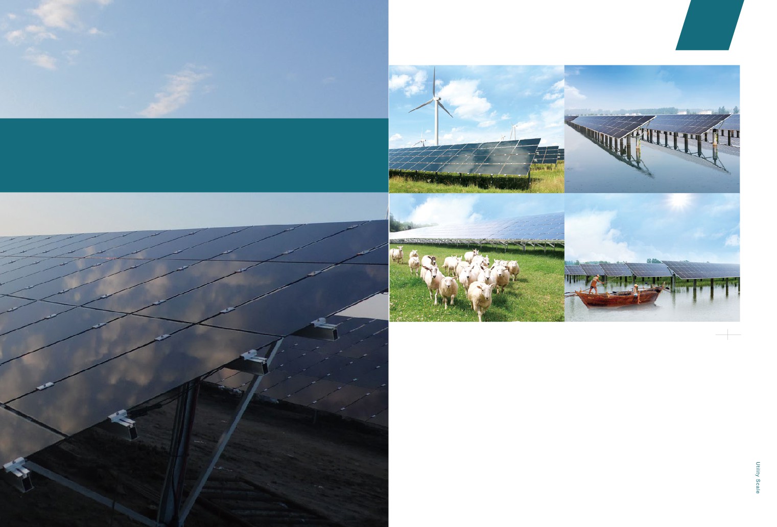
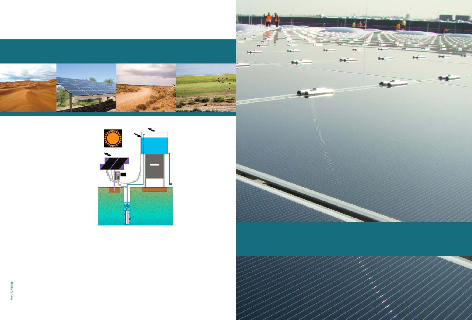
Large utility scale is suitable for installation in waste hills or wastelands, deserts, mudflat areas,
etc., to make full use of the idle land resources.
2 4
3 5
2.1.2 Wind and PV solar power
2.1.4 Hydropower and PV solar
hybrid system
hybrid system
The complementary programs of wind and solar
The effective combination of hydroelectric power
power hybrid system in large utility scales enable the
generation with film power generation, enables
rational utilization of the wind and solar resources. By
hydropower and solar energy to display their
building both solar utility scale and wind power plants
complementary strengths, and to form a mutually
in a given region, they can share the transformer and
complementing power generation model. Using clean
the transmission lines in the region to improve grid
and renewable energy to improve the operational
efficiency and achieve a relatively stable power output.
efficiency of hydroelectric power stations, provide
more access and more effective options for water
conservancy and hydropower enterprises’ innovation
and development efforts.
2.1.3 Farming and PV solar
2.1.5 Fishing and PV solar
After the completion of the ground station, the PV array
Installing the solar power system over the ponds is
blocks the sun's radiation on the ground and effectively
an effective way to use the land resources of the fish
reduces water evaporation, and making the soil
pond. The panels block the sunshine and create a
conditions suitable for ground vegetation to recover. This
shade. This not only enables the fish pond owner to
improves the land use efficiency of the power plant and
get an additional income from power generation, but
25
increases the project output.
also benefits the growth of fish in the pond.
2.1.6 Solar pumping system
Solar pumping system is consisted of panels, controller (invertor), high-performance pumps and pipes, valves, etc.
Water tower
Scope of application:
Water
level
monitor
• Irrigation
• Desert control
An array of thin-film
• Grassland animal husbandry
battery modules
• Urban water views
• Domestic water
Controller
• Sewage treatment
• Sea water desalination
Pump
Solar pumping system illustration chart
2.1.7 landfill thin-film solar plant
2.2
Distributed generation
The effective application of PV solar technology on premises of waste landfills
encounters many difficulties. When the plant is just completed, there could be large
amount of sinking, with uneven local settlements. Hence it is difficult to determine the
bearing capacity of the foundation. The uncertainty of landfill materials and surface
subsidence carries great impact, while at the same time, exudate and methane
fermentation also contribute to the non-utilization of this land resources. As the
degradation and stabilization of landfills require more than 20 years, the construction
of landfill power plants may adopt an inexpensive technical solution, to avoid adverse
factors affecting electricity generation and security of thin-film arrays. Make full use of
26
the land value during the degradation stabilizing period.
2.2.2
Forms of application
Distributed generation mainly include thin film solar panels, DC distribution equipments, inversion
equipments, low-voltage distribution equipments, pressure-rise equipments, environment
monitoring equipments and monitoring system. According to the forms of roof, the installation can
be mainly classified into two types: flat roof and sloping roof.
horizontal installation, maximum
installed capacity
Flat roof
best slanting installation, maximum
generating capacity
Flat roof
dip angle installation, increase
generating capacity
Cement flat roof
Flat roof
Cement flat roof
Cement flat roof
Flat steel tile roof
Tiled sloping roofs
Steel tile sloping roofs
2.3
BIPV
Technical features:
1. The temperature coefficient of thin film panels is smaller than that of crystalline silicon panels. When installed
on the roof, especially in small dip angle installation, heat dissipation of modules is limited, and thin film
modules may have better power output characteristics.
2. Thin film has the advantage of weak light. In the condition of lower solar irradiance, such as in the morning,
evening and rainy days, because of higher optical absorption coefficient of thin film solar cell, the generating
capacity of thin film panels is obviously higher than crystalline silicon panels. Especially when the panels are
28
not installed at the best dip angle, the advantage is more obvious.
Chapter
02
SOLUTIONS
2.3.2
BIPV Applications
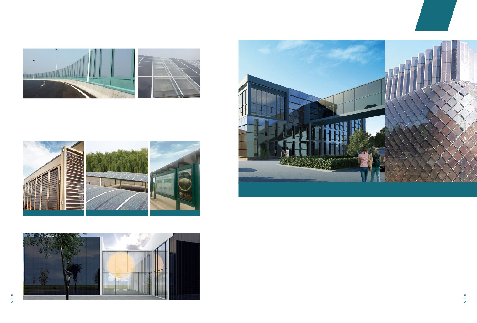
According to the different situations, functions and installation methods, BIPV applications could be divided
into solar curtain wall, solar canopy, solar skylight, solar noise barrier, solar agricultural greenhouse and
etc.
Replace hollow glass, thermal
insulation, noise reduction function
Solar Curtain Wall
Meet the demand of architectural
lighting; provide power and energy-
saving
Solar Skylight
2.3.1
BIPV System Solutions
Provide power and shelter from sun
as building components
Solar Canopy
1. Building Structure Design
• Support structure research for BIPV
Provide power with no additional
• Research and design for advanced BIPV projects
area needed
Solar agricultural greenhouse
2. Electrical Design
• Innovative research for BIPV electrical technology
BIPV Applications
• Supporting electrical design
PV Solar Curtain Wall
3. System Integration Research
• Basic application research of intelligent building
• Integration research for BIPV and building function
Bright Frame PV Solar Curtain Wall
Concealed Frame PV Solar Curtain Wall
Solar Skylight
Technical Characteristics:
With a wide range of panels and installation methods,
the product can provide efficient electricity to the
building while at the same time meeting its functional
requirements such as energy-saving, thermal
insulation, waterproof, noise reduction, etc.
30
31
02
Chapter
SOLUTIONS
Other forms of BIPV application/ highway noise screens
Solar Agricultural Greenhouse
Hanergy Group Headquarters BIPV Renderings
Technical Characteristics:No additional area required, provide power for heat preservation, ventilation,
irrigation systems. It is particularly suitable for areas where power grid is underdeveloped.
Advantages of thin-film panels: Allow red light to pass through and enable crops to grow. Absorb part of
ultraviolet light and reduce UV damage to crops.
Other forms of BIPV application
2.3.3
Hanergy Headquarters BIPV Project
PV Solar Blinds
PV Solar Carport
PV Solar Bus Station
Hanergy Headquarters BIPV Project is located in the Beijing Olympics Forest Park. With installed
capacity of 315kw, the project construction started in March 2014 and completed in October of the
Hanergy Clean Energy Exhibition Center
same year. While maintaining the original layout of the building plane functions, the project makes
good use of different types of PV panels according to the needs of lighting, shading and ventilation.
It is a perfect combination of Hanergy’s PV technology and building.
Floor 1and2 of Tower B adopts the hyperboloid structure, installs custom double-glass panels with
45° diagonal layout, and fitting facade with parametric design.
Floor 3 of Tower B adopts the standard double-glass panels with integral facade appears wavy.
Facade and rooftop of corridor adopts a large size hollow panels with replace of glass curtain wall
elements and with the effect of homogeneous transmittance and a variety of colors.
32
33
Chapter
02
SOLUTIONS
High power generation
2.4
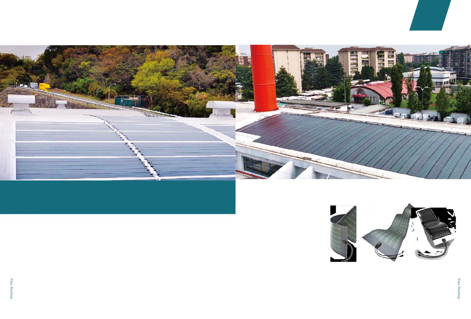
Flex Rooftop
High efficiency CIGS
· Efficiency as high as 16%
High performance
2.4.1
Advantages
· Performs in all light conditions
· Shade tolerant
Designed specifically for rooftops
Light weight
Covers entire roof area
· Less than 4kg/m2
· Lays flat. No tilt required
· Minimum panel spacing required
Integrates with roofing surface
· No mounting hardware
· No roof penetrations
Low installation costs
· Superior wind resistance
· Flexible. Fits many roof types
Direct Adhesion
· Innovative architectural effect
· Eliminating racking reduces BOS cost
34
35
02
Chapter
SOLUTIONS
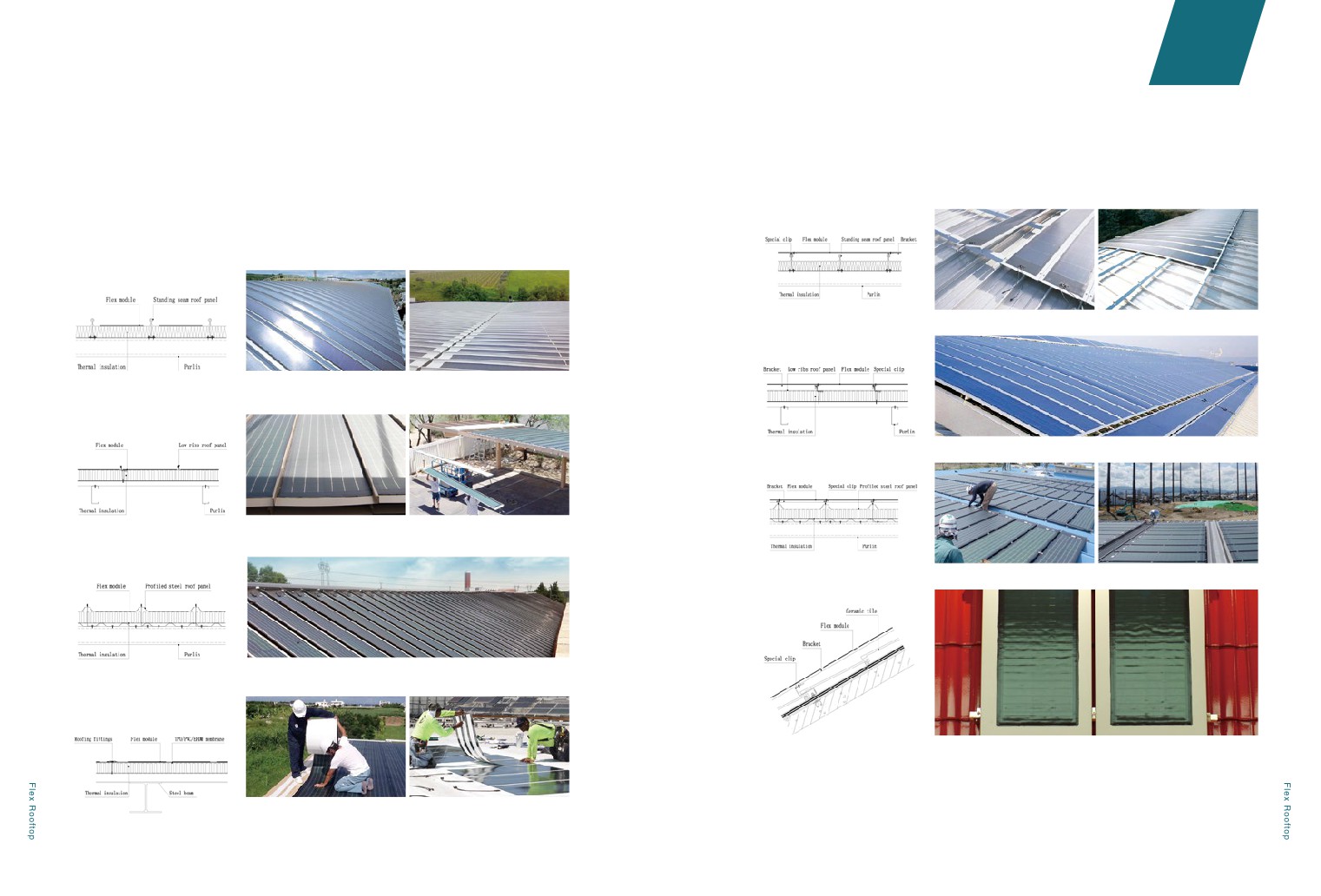
2.4.2
Installation Method
Platform Attachment
Stick flex panels to a platform; then use brackets and clips to fix the platform onto the rooftops.
Apply to the rooftops below:
Direct Adhesion
Peel the release paper off the flex panel and stick the adhesive surface to the rooftops.
1) Standing Seam Rooftop
Apply to the rooftops below:
1) Standing Seam Rooftop
2) Low Ribs Rooftop
2) Low Ribs Rooftop
3) Profiled Steel Rooftop
3) Profiled Steel Rooftop
4) Ceramic Tile Rooftop
4) TPO/PVC/ EPDM Membrane
Rooftop
36
37
Chapter
02
SOLUTIONS
2.5.1
solar sunroof solution
Advantages of CIGS technology
•cell mass production efficiency 16.4% (2014)
•light, flexible, substrate only 50μm
•can be cut and customized
•UltraWire ™ design, positive and negative connection is convenient
PV solar sunroof
2.5
Vehicle and Yacht application
39
Application scenario—ventilation
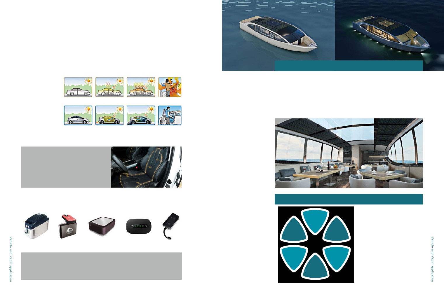
In summer, the in-car temperature can be very high(70
℃ ) when the vehicle is parked under the
sunshine for some time. Then you need the automatic ventilation system which the solar sunroof can
bring. When parking, the solar sunroof will supply power to ensure air circulation through the ventilation
fan. The in-car temperature can effectively drop to 20
℃ and the surplus power can replenish the
2.5.2
Yacht/ ship application
battery to prolong its service life.
Without solar sunroof
when parking
temperature rises
stuffiness increases
Environmental protection:Solar sightseeing ships benefit the ecological environment and sustainable
development as they produce zero emission and zero pollution.
Economic benefit: Solar vessels reduce the energy consumption leading to lowered operational cost of
the vessels.
Social effect: pure solar yacht can raise concerns of the public about environmental protection and
with solar sunroof
when parking
cooling
establish a good social image.
1、generates energy with solar
2、starts the ventilation system
3、switches on the air conditioner
4、no longer have the stuffy
power
and vents away hot air with solar
with the smart key before driving
feeling when getting in the
power
car
Application scenario—seat heating
In winter, the cold temperature not only leads to the
uncomfortable driving experience, but also tends to
damage the engine. Then you need the seat heating
and car-body preheating functions which the solar
sunroof can bring.
2.5.3
Power solutions for mobile applications
Application scenario—power supply to electronic equipment
Trickle
charge
system
Security
Heating
Application scenarios:
lighting/
Ventilation
power supply
Air
motor homes, bus, cold chain car,
system
Conditioning
insulated truck, urban railway, special
Car fridge
Data recorder
Air cleaner
WIFI
GPS security locator
CIGS
vehicle
Intelligent
Extended
modular
With the development of the automobile industry, electronic devices in cars demand for electricity
range
System solution introduction:
application
increasingly. Solar sunroof can effectively collect solar energy and transform it into other forms of
Cold chain/
include solar panels, installing suite,
energy to supply the air conditioner or battery in the car. Therefore, this system is also suitable for
Heat
preservation
controller, cable
Hybrid Electric Vehicles or Pure Electric Vehicles.
40
41
Chapter
02
SOLUTIONS
· The power generation rate of CIGS cell is high. It can integrate perfectly with car roof thanks to its light
weight, thin shape and flexibility.
· It can prolong the service life of the storage battery by preventing electricity lost.
· It can charge the vehicle navigation system, vehicle traveling data recorder, entertainment system,
digital products, etc.
· When parking in summer, the controller can ventilate the car automatically to clean the air.
2.5.3
Auto parts market application solutions
· Outdoor emergency system.
Product introduction
· It is portable and exquisite so that it is easily packed into the car trunk and suitable for power supply
and emergency relief purposes.
· It is possible to be the vehicle’s standard accessories thanks to its perfect design and power supply
features.
· Its energy storage system supports 5V, 12V, 110V voltage output.
· It can supply lighting and charging (mobile, pad, camera, laptop and so on).
No need for the screw to penetrate the car roof,
Easy to attach, can be well-fitted with a variety of roof shapes
causing no damage to the roof
Product features
Clean energy-----transfer solar energy to electric energy
Environmental protection----- zero carbon emission & zero pollution
High percentage conversion rate-----CIGS solar cell (the world’s highest efficiency)
Portable----- weighs less than 2KG and the size matches all types of trunks
Multi-purpose ----meet different needs of car owners
Expandability----increase panels to meet different power needs
Vehicle can stop at any position, the panels require
Panel installation does not affect the appearance of
no particular installation angle
the vehicle body
42
43
02
Chapter
SOLUTIONS
2.6.1 General View
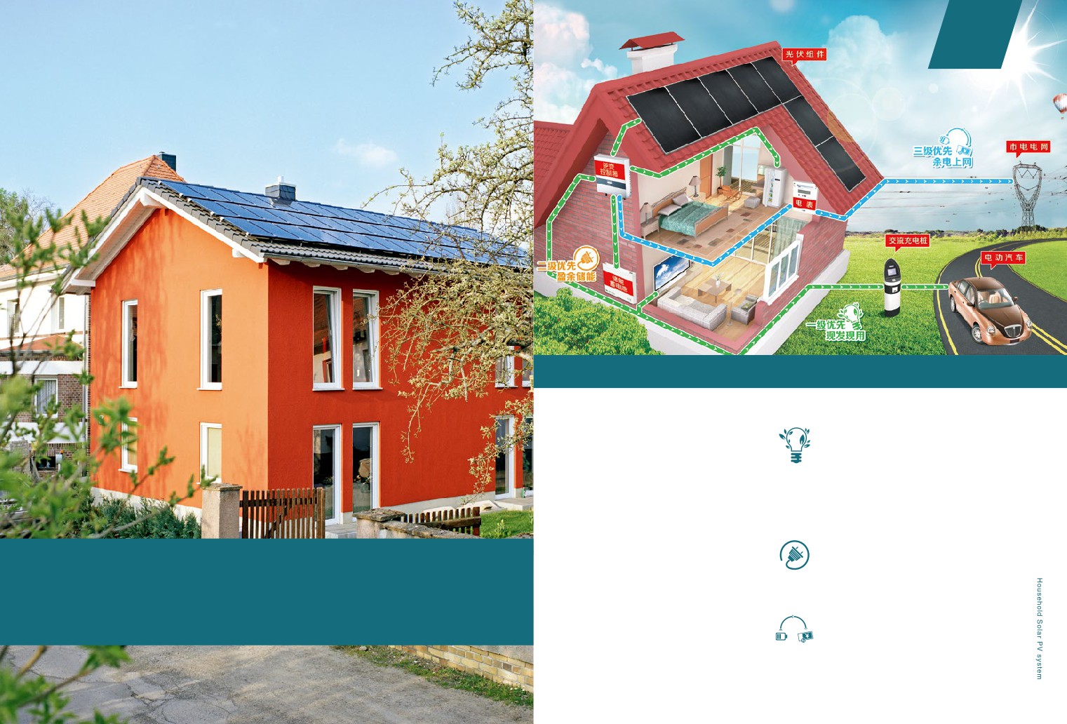
A Hanergy Household Solar PV system
Level 1 priority: Generate electricity for
household appliances
· Is a mini power station installed on the top of
your private residence, which utilizes thin-film
Solar PV panels absorb the sunlight and
transform it to DC (direct current). The inverter
solar panels to absorb the sun’s energy and
converts DC to AC (alternating current), which
generate it to electricity.
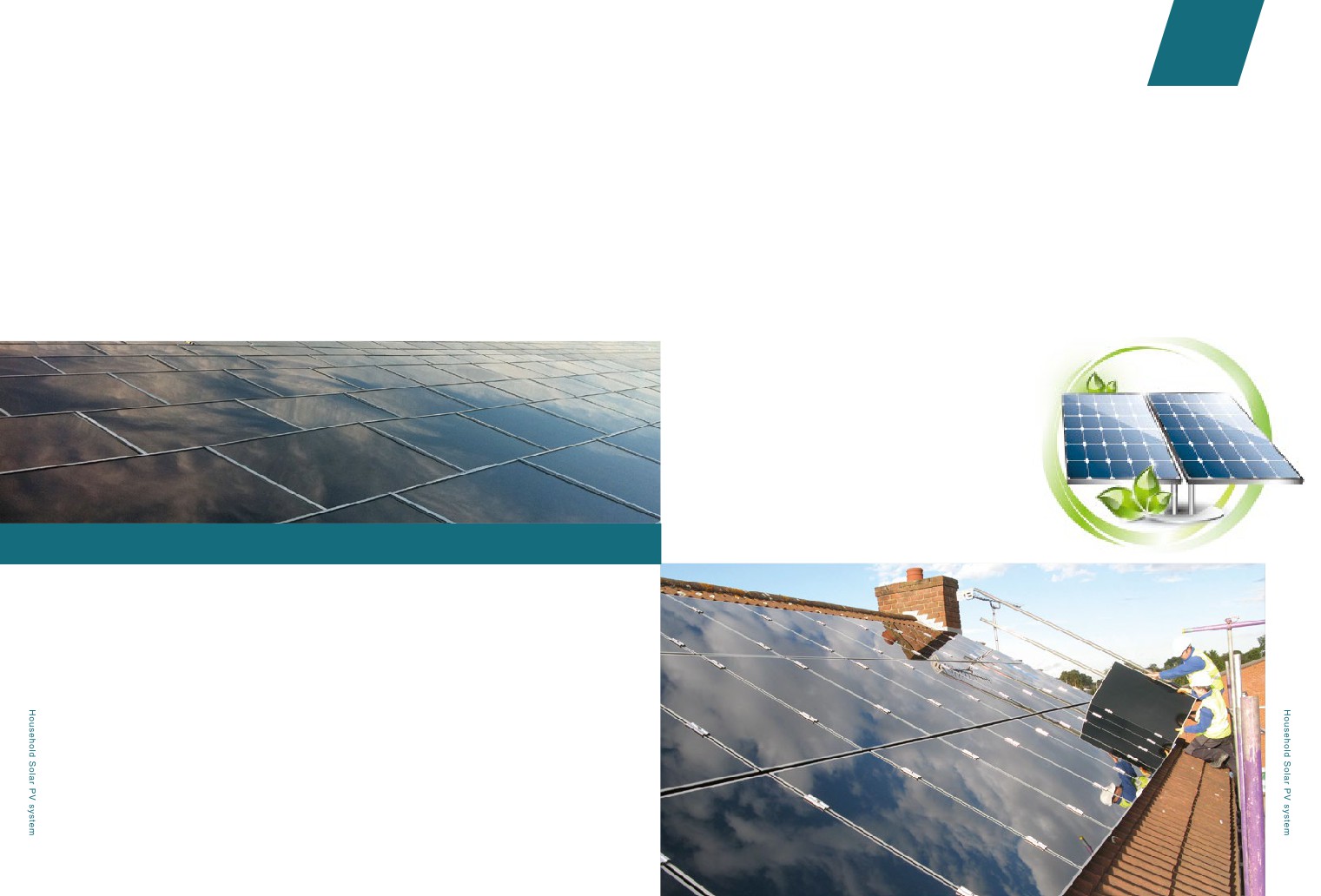
can supply all your household appliances like it
· Can be installed in any places exposed
used to.
to sunlight, such as your roof top, balcony,
Level 2 priority: Surplus energy storage
garden, carport top, etc.
surplus electricity unconsumed by home
· Is a power station that you can own in 2
appliances will be stored in batteries for use at
weeks and can serve you for as long as 25
night or during raining or snowy days.
2.6
Household Solar PV system
years, unremittingly.
· Doesn't just save you money. Thanks to a
Level 3 Priority: Access to the Grid for
Government backed scheme, it earns you
excessive electricity
money too.
When the battery is full, the system will
automatically export the excessive electricity to
the grid and earn additional income.
45
02
Chapter
SOLUTIONS
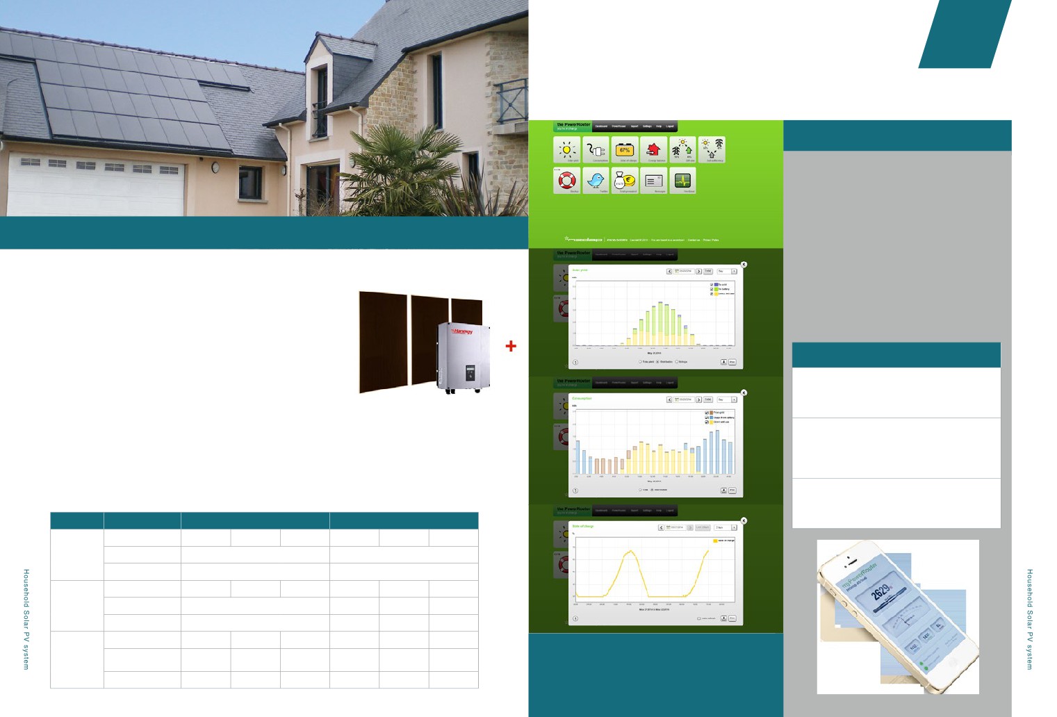
③ Monitoring
Your solar generation and electricity consumption will be
updated in real time by your monitoring system.
Hanergy monitoring system can enable you to:
1.Obtain the data of generated & saved energy all day
2.6.2
Hanergy Household Solar PV system
long;
2.Get other data, such as your daily contribution in
A Hanergy Household Solar PV system is basically composed of 3 parts:
respect of carbon emission;
3.Be aware of the appropriate time to cleanse your
① Hanergy Thin-Film Solar Panels
system;
Hanergy Thin-film panels (including standard panels, color panels, transparent
4.Know about the breakdown of the system in time.
panels and flexible panels) have outstanding low-light behavior, steady
guaranteed performance, and an attractive visual appearance, making them
A monitoring system:
perfect for homes. The 25 year warranty covers the panels for up to 80% of their
Is easy to use: It can be easily monitored through your
original output.
PC or other mobile devices, whose software/Apps can
be quickly downloaded and installed.
② Inverter and other electrical equipment
Can realize long range control: It incessantly sends
The inverter turns the Direct Current into Alternating Current (AC) so it can be used within the home.
system data to your devices through internet.
Meanwhile, the information can be shared between all
Other electrical equipment such as controller, combiner box, fuse board, etc. can make the system complete and
your indicated devices.
ensure the performance.
Gives excellent performance: It can automatically
Standard Configuration Parameter Table (Using Solibro 115W Panel as example)
generate intuitive histograms from data and can record
failure with its cause.
Common Grid-connected system
Energy storage Grid-connected system
System Capacity
3.45kWp
4.14kWp
5.75kWp
3.45kWp
4.14kWp
5.75kWp
Size & Weight
Controller Size
545x504x149mm
765x504x149mm
Controller Weight
15.5kg
20.5kg
CIGS Moudle Capacity
30
36
50
30
36
50
DC Side
Battery Capacity
N/A
400Ah
600Ah
800Ah
Output at Night
N/A
4.4kWh
5.3kWh
11kWh
Max AC Output Current
13A
16A
25A
13A
16A
25A
3-Phase Mutual
AC Side
Adopted
Adopted
Adopted
Adopted
Adopted
Adopted
Inductor
Isolation Transformer
Adopted
Adopted
Adopted
Adopted
Adopted
Adopted
46
47
Chapter
02
SOLUTIONS
Monitoring system instructions
Hanergy intelligent monitoring system is composed of the local monitoring system and the network remote
monitoring system. The local monitoring system allows you to check the generation data and to set parameters
Saving
through the inverter LED screen display or through your PC (with cable connection to inverter). The network
At the same time, you can save money and resources as well:
remote monitoring system helps you to visit the system’s server through your PC, tablet computer or smart
phones, so as to look over the current, accumulated and statistical data.
• Get free electricity from the sun and save up to 50% on your energy bills
• Decrease your risk of future increases in electricity rates
Hanergy monitoring system displays all the key data of electrical equipment in the terminal of the controller
and upload it to the server. The Hanergy thin-film PV power station owner can get all information, such as the
• Save up to one tonne of carbon per year
hourly output, the daily system efficiency, the battery (if needed) state, self-using power of inverter, uploaded
power, etc.. It greatly helps the owner and the maintenance team to monitor the quality and the efficiency of all
equipment.
Let's take a closer look at why solar is the ultimate feel-good investment:
Hanergy monitoring system unremittingly ensures the maximized interest of the owner.
For 2.88kW system fit for a semi-detached home in Maidstone, Kent, you can make an annual return of£623.
This will help pay back the entire cost of the system in roughly 8 years.
Annual Benefit Breakdown
Feed-in Tariff Income------£367
Export Tariff Income -------£61
Electricity Bill Savings------ £195
= Total Annual Benefit------ £623
% Return on investment:12%
2.6.3
Earning and Saving
Earning
Every year, with a Hanergy solar system you will make money in three distinct ways:
Obtaining “FIT (Feed-In Tariff)”
For every kWh that you produce, whether you use it or not, you can get corresponding revenue called FIT. The
FIT value depends on the government backed scheme.
Obtaining “Sell electricity tariff”
For every excess kWh that you sell to the grid, you will earn additional revenue.
Reduce 50% daily electricity costs
Your solar system will generate free electricity to your household appliances, so you SAVE buying nearly 50%
from your expensive utility each year.
48
49
Chapter
02
SOLUTIONS
1 Grid interconnection
2 System design and budget
Hanergy IKEA Store @ UK
application guidelines
analysis
As a one-stop
6 Perfect after-sales
3 Panels electrical equipment
shop, Hanergy
service
and other accessories provision
provides:
5 Monitoring system and
4 Site support during the construction
data analysis
2.6.4
One-Stop Service
Hanergy Carrefor Store @ Poland
Selecting the Hanergy Household Solar PV System means the procurement of not only a high quality product, but also
2.6.5
Hanergy Stores around the World
Hanergy’s standardized and systemized services.
In order to make it a pleasant experience for the customer to purchase this affordable solar system for your home, Hanergy
Hanergy wants to inspire you and enable you to live a more sustainable life at home and
offers to provide a full range of installation services. We will employ next generation solar technology, create an expert team
help you save money, reduce waste and energy consumption.
and constantly improve our services.
Step 1: Pre-sales advisory service
Step 5 Site operation
Includes: popularization of the use of clean energy,
Includes: equipment transportation, constructors dispatch,
photovoltaic products and system introduction, installation
on site construction, provision of protection measures
procedure explanation, etc...
Step6 Data monitoring
Step 2: Measurement and calculation of roof top
Includes: provision of data monitoring system, immediate
Includes: Load calculation, recording of near shadings,
alert of data exception
professional mounting recommendation
Step 3 System design and budget analysis
Step7 After-sales service
Includes: array design, selecting & matching of electrical
Includes: service manual, quality and performance
equipment, estimation of total expense
guarantee, life-long maintenance
Step 4 Application for grid connection
☆ We provide support if any issues arise with your system.
Hanergy Experience Store @ China
50
☆ Don’t even worry about it. Leave all those application
Over a hundred Hanergy stores are ready to
troubles to the Hanergy expert team!
be opened this year.
02
Chapter
SOLUTIONS
2.7.1 Rapid Deployment System (RDS)
2.7
Consumer Application
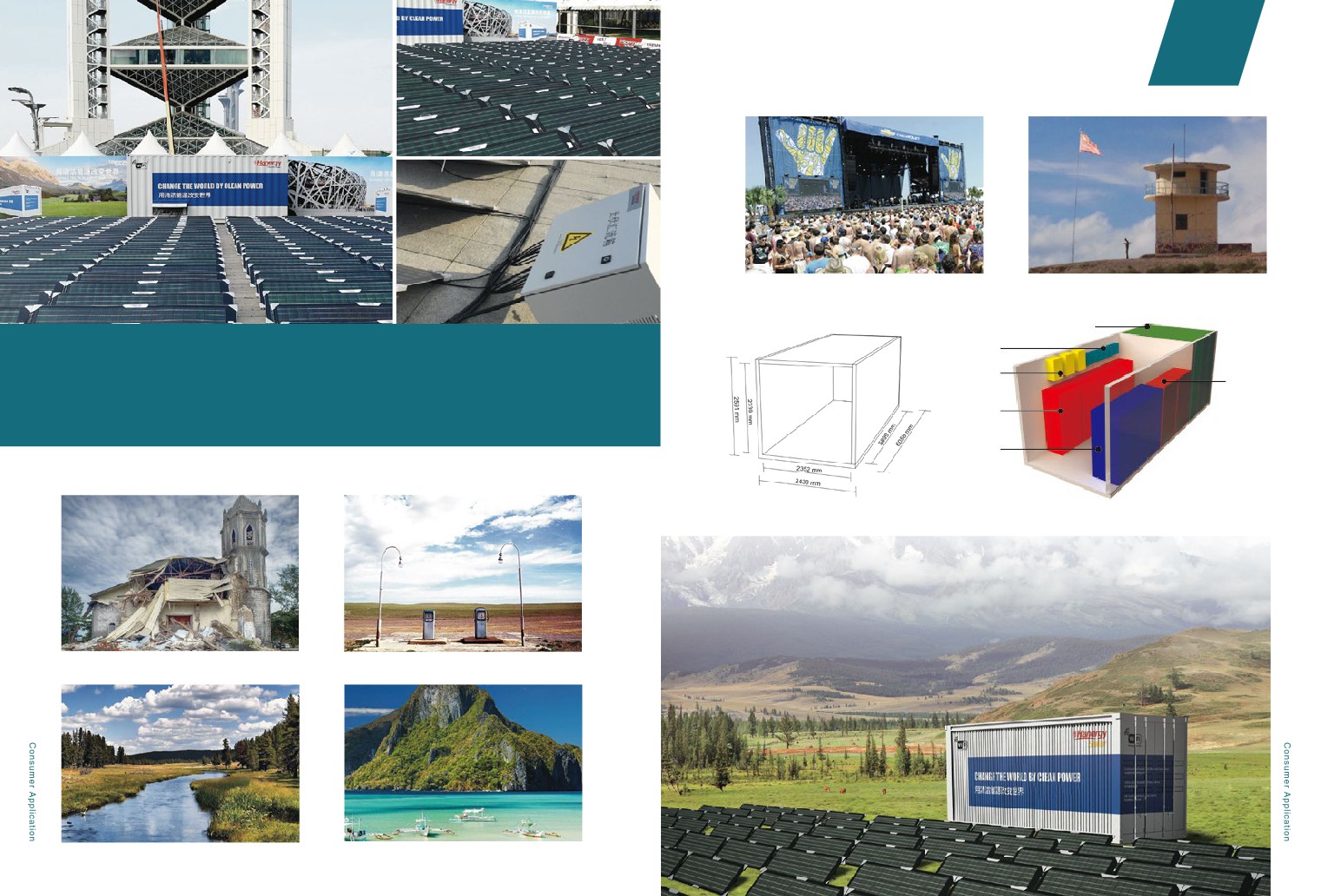
The rapid deployment system (RDS) is an emergency power supply solution, which is designed to assist
disaster relief operations around the world, or to provide power to off grid areas on a short/long term
basis.
RDS ADVANTAGES
Light Weight
The system weighs less than 10
tons, convenient for sea, land & air
Super light
30s rapidly pack & deploy
Portable
transportation.
Compact
All system components are fixed & stored
in a 20ft container.
Easy to Pack & Deploy
It takes 5 non-skilled workers less than 3
hours to deploy the whole system.
High Power Output
The theoretical power output is 70 KWH/
sunny day & 12KWH/cloudy day.
Note:
· The system power output varies in
different places.
· The measured power output
· KWH/day ( Sunny, Sep 13th, at
Formula E, Beijing )
·
15KWH/day ( Hazy & Cloudy, Sep
25th, at ERExpo, Beijing )
53
Chapter
02
SOLUTIONS

Off-Grid Locations

Border Post
Solar Module
RDS adopts the cutting-edge thin-film technology - CIGS flexible thin-film solar modules (100W, 2.6KG/piece, by
Controller
Global Solar Energy) to guarantee the rapid & high power generation during the day.
Invert
Battery
The whole system is fixed within a 20 foot container and is easy for rapid transportation & deployment.
The 19.2KW system consists of 192 pieces of flexible thin-film modules, MPPT charging controllers, bi-directional
Battery
inverters, battery storage systems, string boxes & AC distribution cabinet, etc.
Electricity
The emergency power supply solution is specially designed for the below situations:
20ft Container 3D Image
CUSTOMIZATION
Hanergy provides the system customization upon clients’ requests,
which covers:
1. System size
2. Container size & coating

Earthquake Diaster Relief

Remote Areas without Electricity
3. Auxiliary functions: WiFi, radio communication, etc.

Prairies / Pasturing Areas

Island and lslets
54
55
Chapter
02
SOLUTIONS
2.7.2 Solar Camping Kit
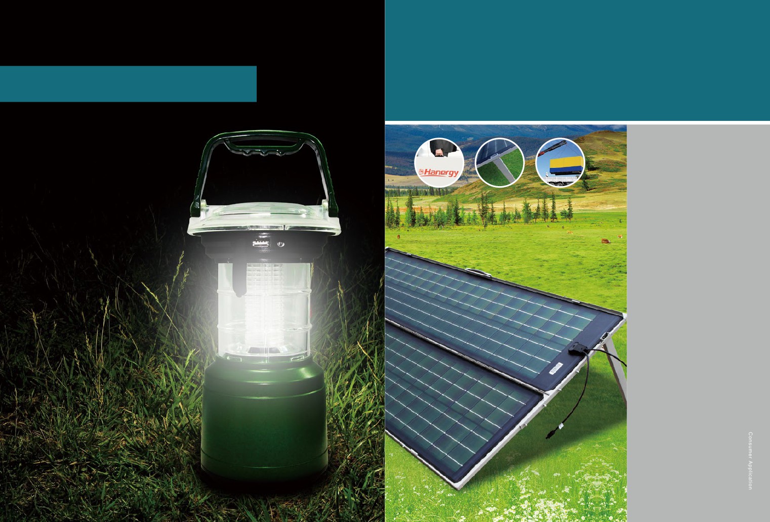
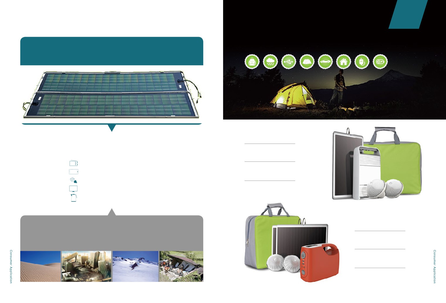
With the idea of energy-efficiency and environmental protection, solar camping kit is portable, convenient, has long
service life, and ensures you to enjoy outdoor life freely.
It can generate one kilowatt electricity per day!
KP3-033
What can one kilowatt electricity do?
Charging Time by Solar:
20-22 Hours, depending on the sunlight.
One month continuous radio play
Single Lamp Working Time:
200 hours recharge of iPhone 5s
25-27 Hours.
100 hours lighting for 10W energy-saving lamps
10 hours play of 55-inch LCD TV
One hour continuous burning of a 1000W kettle
KP3-105
Where can it be applied?
Earthquake-stricken and remote areas where electricity is lacking,
Charging Time by Solar:
border posts, and any other open areas where electricity is needed
15-17 Hours, depending on the sunlight.
Single Lamp Working Time:
28-30 Hours.
56
57
Chapter
02
SOLUTIONS
CP1 - 060C/E
This solar charger is an appropriate
partner to your outdoor activities. It
could be charged by solar repeatedly
in many flexible ways, such as
hanging on knapsacks or adsorbed on
windows, because it is equipped with
a sucker and a hook. Besides, it has a
series of connectors for your different
electronics.
Charging Time by Solar:
60-62 Hours, depending on the
sunlight.
Charging Time by Adapter: 4-5 Hours.
Lamp Working Time: 40 Hours.
Battery Specification: 3.7V/2400Ah.
Charging Time for iPhone: 4 Hours.
LP2-325A
This is a solar camping light and
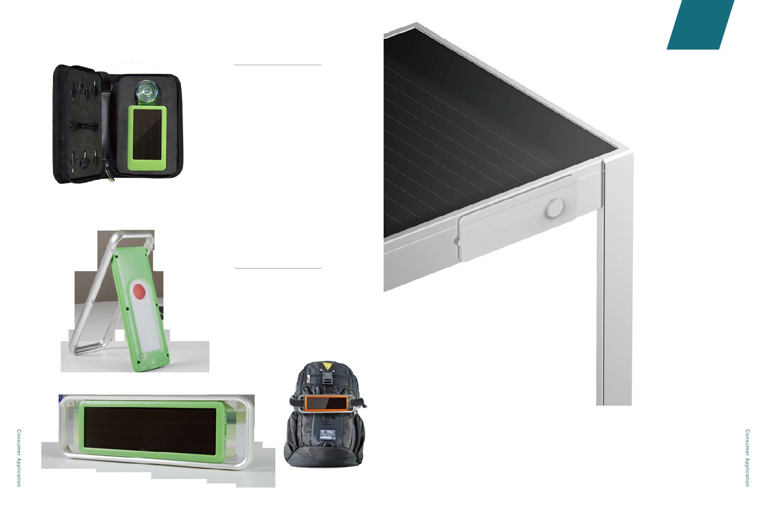
2.7.3 Solar Smart
charger. It is appropriate to outdoor
lighting and mobile phone charging.
Table
Charging Time by Solar:
28-30 Hours, depending on the
sunlight.
T-S-A-62M-07
Lamp Working Time: 9-11 Hours.
Solar smart table stores the energy into integrated
battery. You may charge your electronics by
connecting USB on the table. It provides you more
convenient power supply solution outdoors.
Coffee Table
Size:661mm×647mm×736mm
Built-in batter
Charge 10 pieces of iPhone (3 hours/piece)
Charge 2 pieces of iPad (8 hours/piece)
58
59
02
Chapter
SOLUTIONS
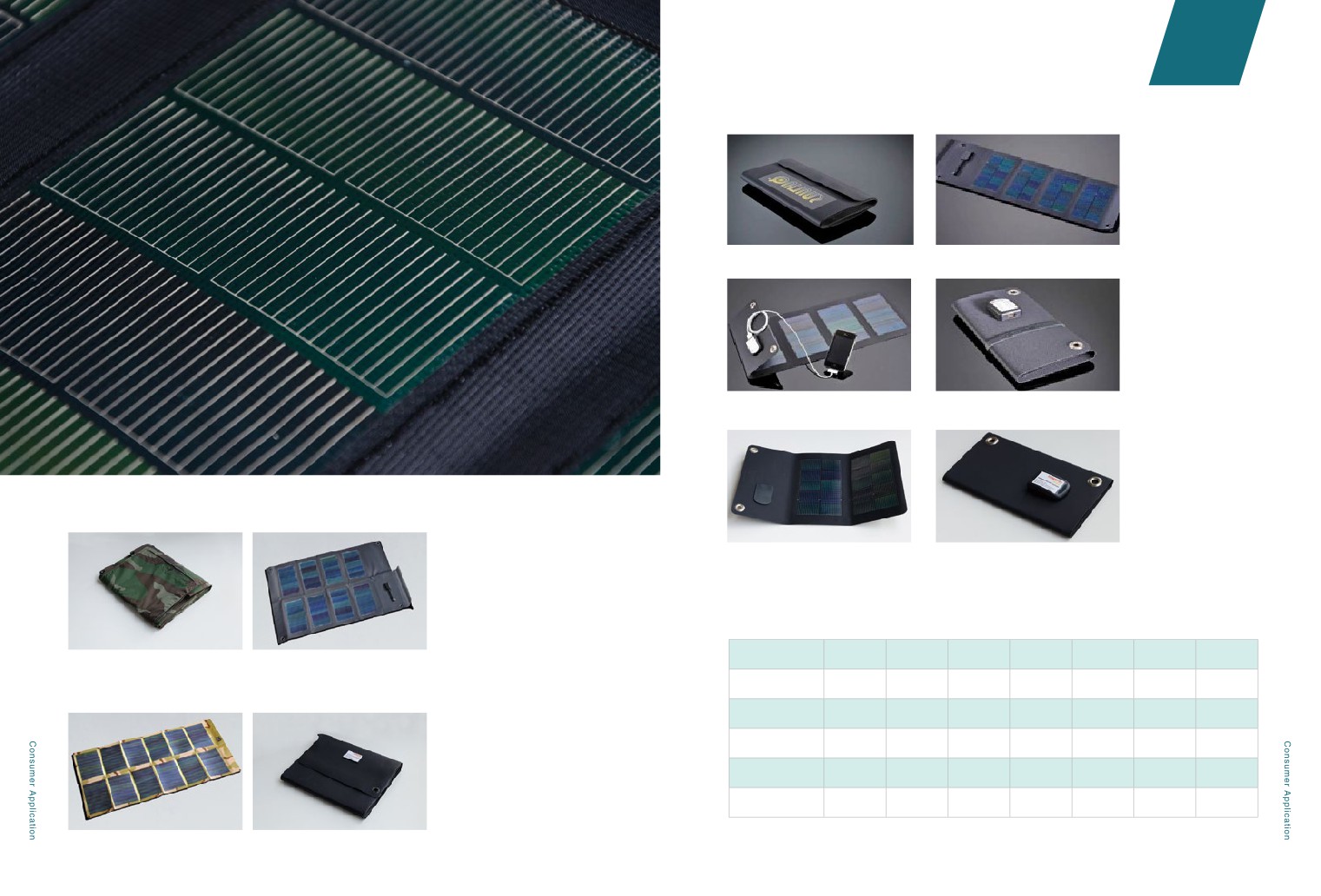
6.5W Solar Charging Bag
2.7.4 Flexible Solar Charging Bag
4W Solar Charging Bag
2W Solar Charging Bag
30W Solar Charging Bag
12W Solar Charging Bag
Product Specification
Flexible Solar
2W
4W
6.5W
12W
25W
30W
62W
Charging Bag
62W Solar Charging Bag
25W Solar Charging Bag
Voltage
5V
5V
15V
15V
16.5V
18.8V
20V
Current
400mA
800mA
433mA
800mA
1500mA
1600mA
3100mA
Open Size (cm)
35.6 x 22.9
61.0 x 22.9
73.6 x 22.9
73.6 x 45.7
104.8 x 54.6
111.8 x 53.3
133.3 x 76.2
Folding Size (cm)
22.9 x 12.7
22.9 x 12.7
22.9 x 12.7
22.9 x 12.7
26.7 x 21.6
26.7 x 21.6
36.8 x 21.6
Weigh(g)
113
179
198
312
737
907
1451
60
61
REFERENCES
3.1
Utility Scale
3.2
Distributed generation
3.3
BIPV
3.4
Flex Rooftop
3.5
Vehicle and Yacht application
03
Chapter
REFERENCES
3.1
Utility Scale
Qinghai Hainan prefecture thin-film ground power generation project (installed capacity: 150MWP /
amorphous silicon thin-film panels / phase one (50MWP) was completed in 2012)
Greek thin-film ground power generation project (installed capacity: 4MWP / amorphous silicon thin-
film panels / completed in 2012)
Ningxia Wuzhong thin-film ground power generation project (installed capacity: 20MWP / amorphous
silicon thin-film panels / completed in 2012)
65
03
Chapter
REFERENCES
Guangdong Heyuan Hanergy Golden Sun thin-film power generation project (installed
capacity: 5.18MWP / amorphous silicon thin-film panels / completed in 2012)
Xiangyang roofing thin-film power generation project (installed capacity: 10MWP /
amorphous silicon thin-film panels / completed in 2014)
Nongfu Spring Water Co., Ltd. Guangdong Wanluhu thin-film power generation project
(installed capacity: 4.82MWP / amorphous silicon thin-film panels / completed in 2013)
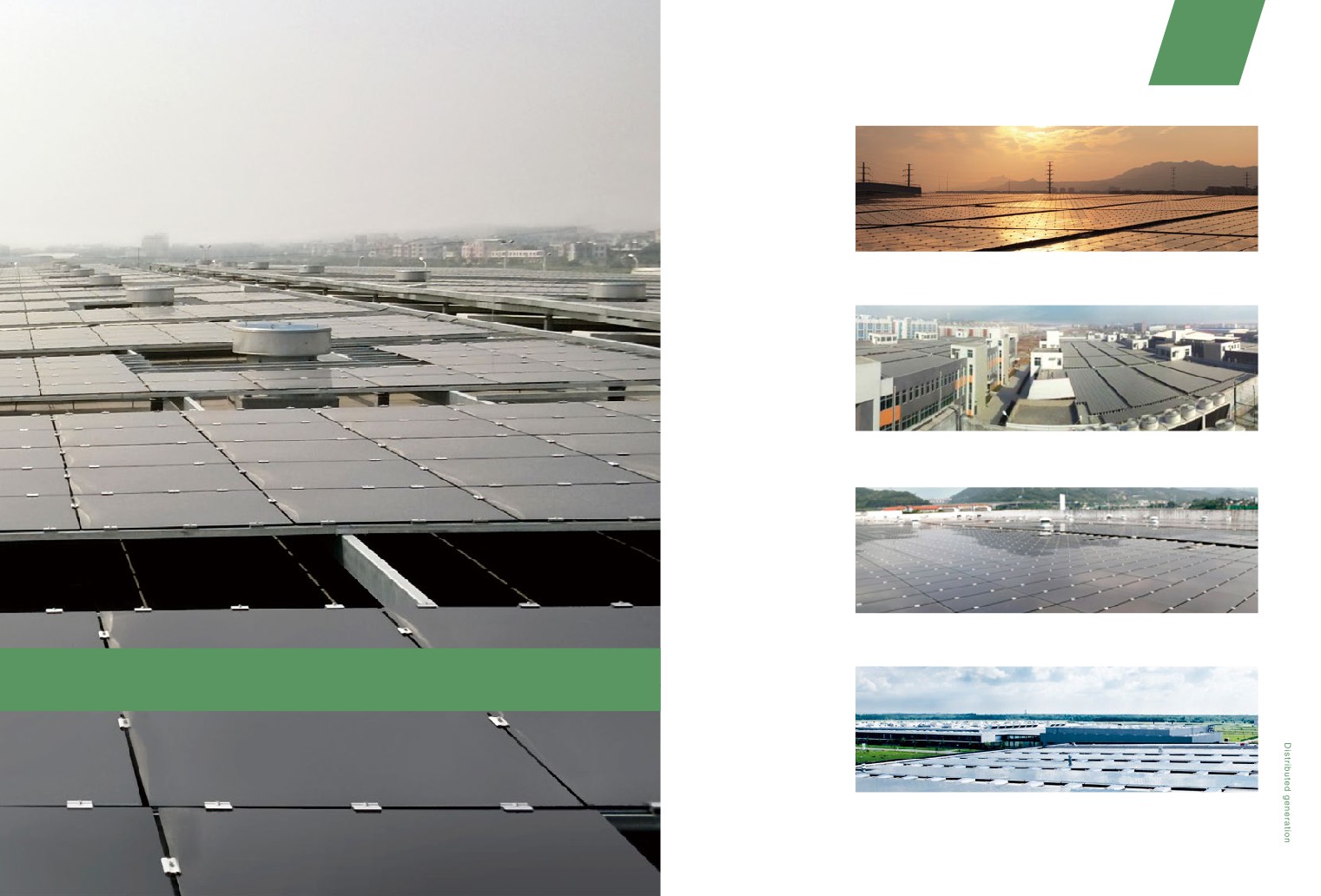
3.2
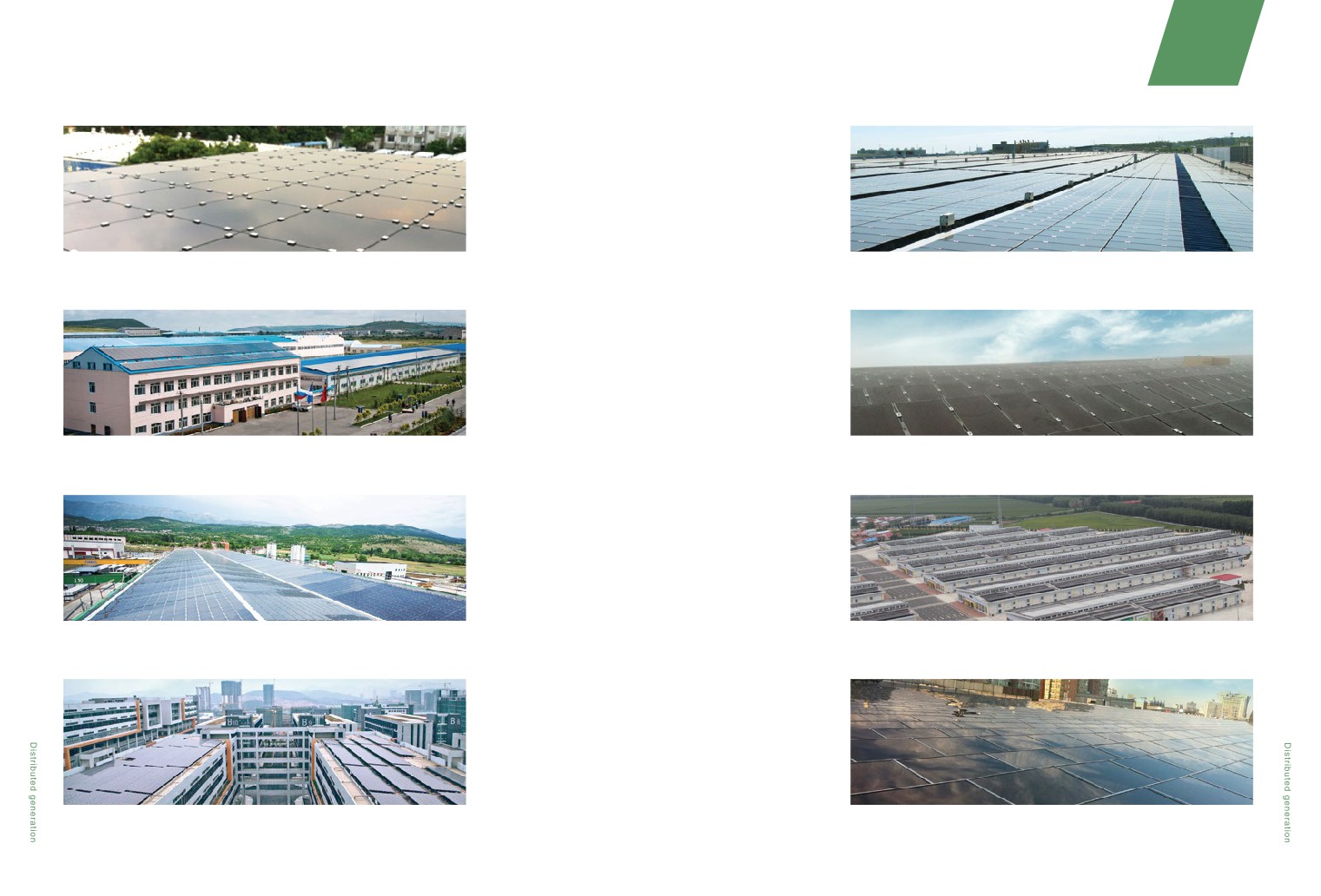
Distributed generation
German Thalheim factory roofing thin-film Solibro power generation project (installed capacity:
1.3MWP / copper indium gallium selenide panels / completed in 2012)
67
03
Chapter
REFERENCES
Honda thin-film power generation project (installed capacity: 17MWP / amorphous silicon
Haikou Hanergy thin-film power generation project (installed capacity: 3MWP / completed
thin-film panels)
in 2013)
Russia Ussuriysk thin-film solar energy roofing power generation project (installed
Hanergy Yucheng thin-film power generation project (installed capacity: 3MWP /
capacity: 100KWP / 2012 for completion)
completed in 2013)
L'Aquila, Italy roofing thin-film power generation project (installed capacity: 837KWP /
Hanergy Heilongjiang Shuangcheng thin-film solar power project (installed capacity:
amorphous silicon thin-film panels / completed in 2012)
5.14MWP / completed in 2014)
Guangzhou accelerator thin-film power project (connected to the Grid in 2013)
Thin-film rooftop solar power project for IKEA stores in Tianjin (installed capacity:
616KWP / completed in 2014)
68
69
03
Chapter
REFERENCES
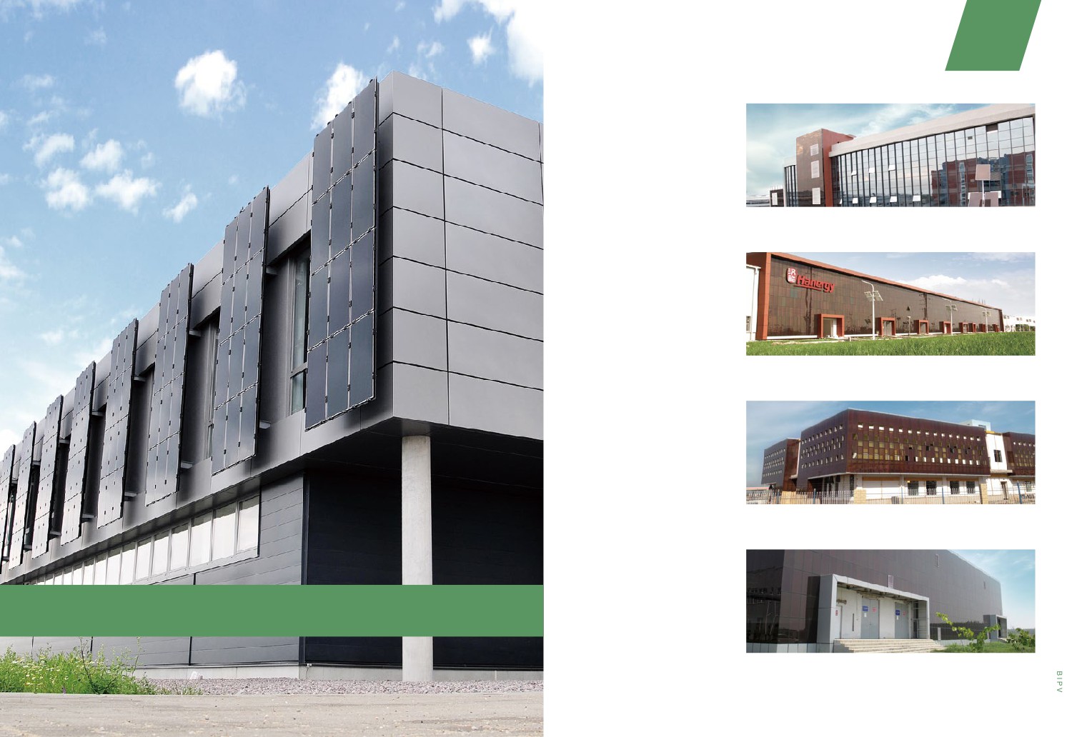
Guangdong Hanergy BIPV curtain wall project
Jiangsu Wujin Hanergy BIPV curtain wall project
Turpan BIPV curtain wall project
3.3
BIPV
Shandong Yucheng Hanergy BIPV curtain wall project
71
03
Chapter
REFERENCES
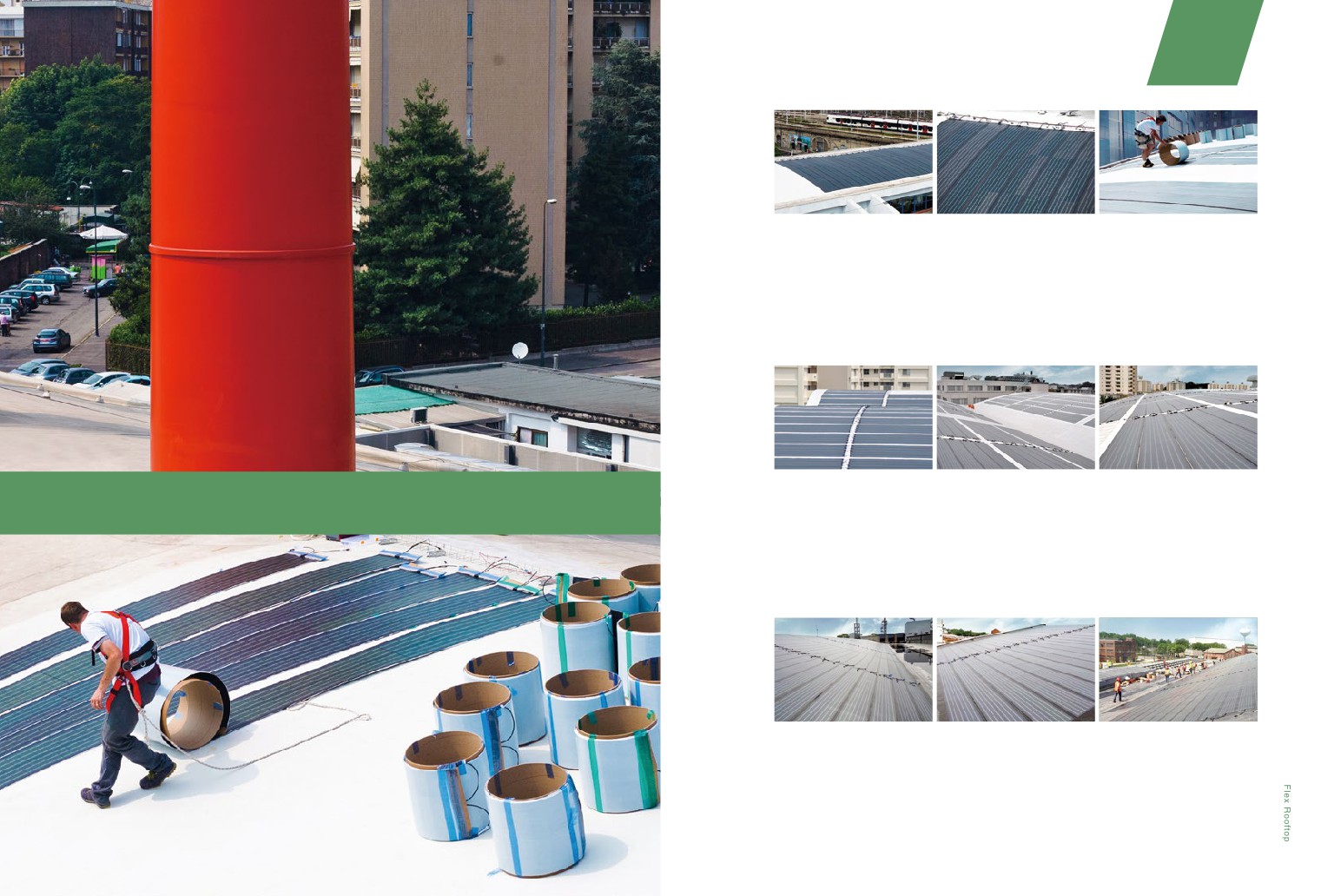
Milan, Italy
• Installation: June, 2011
• Modules:300W PowerFLEX ™ 6
• Power:19.8kWp
• Roofing Material: TPO membrane
• Installation Method: Direct adhesion
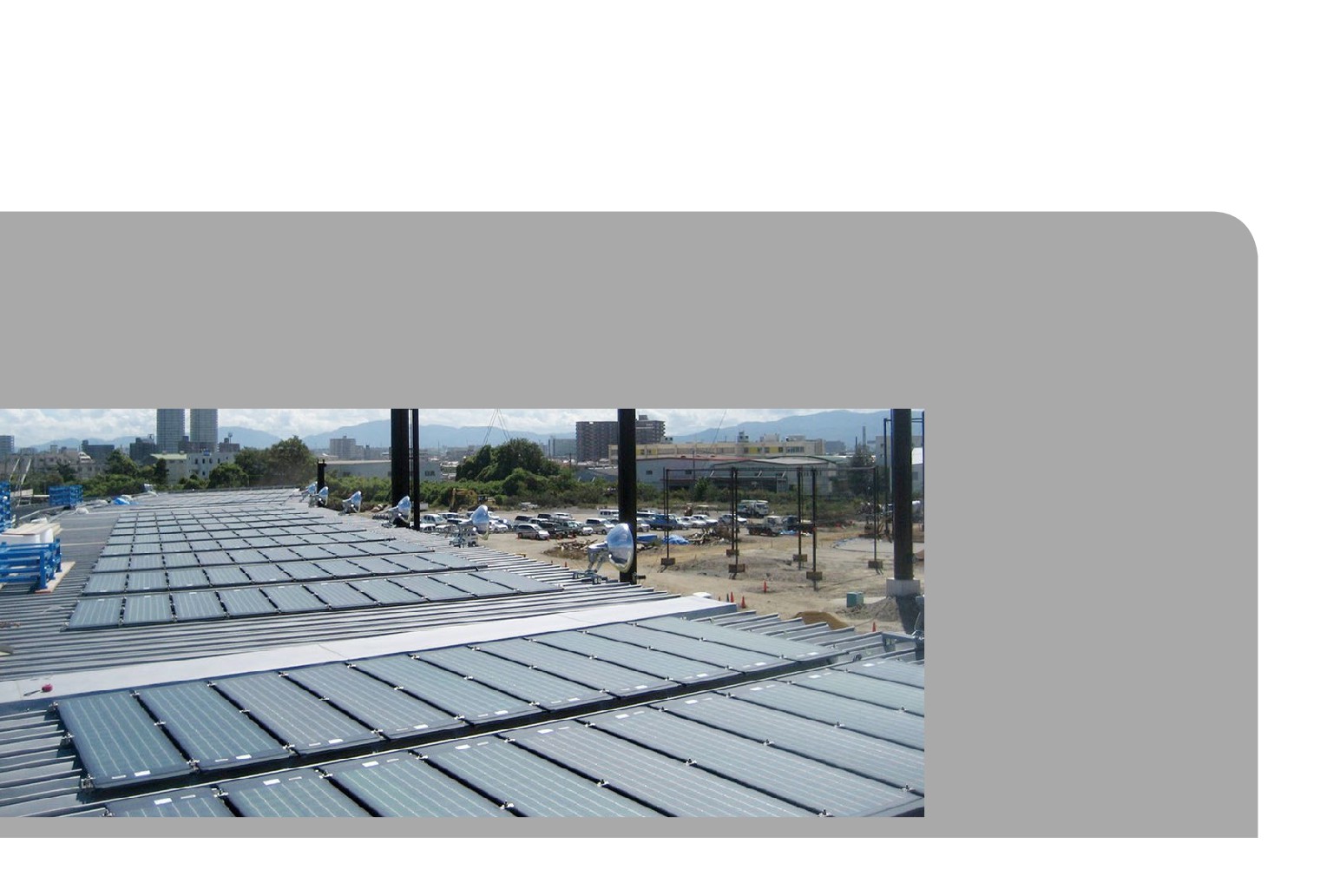
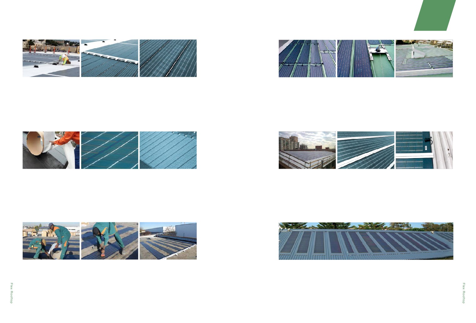
Yokosuka, Japan
• Installation: April, 2012
3.4
Flex Rooftop
• Modules:275W PowerFLEX ™ 6
• Power:400kWp
• Roofing Material: TPO membrane
• Installation Method: Direct adhesion
New Jersey, USA
• Installation: May, 2012
• Modules:275W PowerFLEX ™ 6
• Power:350kWp
• Roofing Material: EPDM membrane
• Installation Method: Direct adhesion
73
03
Chapter
REFERENCES
Hawaii, USA
• Installation: October, 2011
Italy
• Installation: September, 2011
• Modules:250W PowerFLEX ™ 6
• Modules:275W PowerFLEX ™ 6
• Power:100kWp
• Power:15kWp
• Roofing Material: Elastomeric coating
• Roofing Material: Standing Seam Metal
• Installation Method: Direct adhesion
• Installation Method: Direct adhesion
Zaandam, Netherlands
• Installation: October, 2011
Milan, Italy
• Installation: December, 2011
• Modules:90W PowerFLEX ™ 2
• Modules:250/275W PowerFLEX ™ 6
• Power:90kWp
• Power:70kWp
• Roofing Material: EPDM membrane
• Roofing Material: Profiled Metal
• Installation Method: Direct adhesion
• Installation Method: Platform attachment
Paris, France
• Installation: November, 2011
Sydney, Australia
• Installation: January, 2013
• Modules:275W PowerFLEX ™ 6
• Modules:70W FLEX-01N
• Power:5kWp
• Power:1.7kWp
• Roofing Material: Modified Bitumen
• Roofing Material: Profiled Metal
• Installation Method: Direct adhesion
• Installation Method: Platform attachment
74
75
03
Chapter
REFERENCES
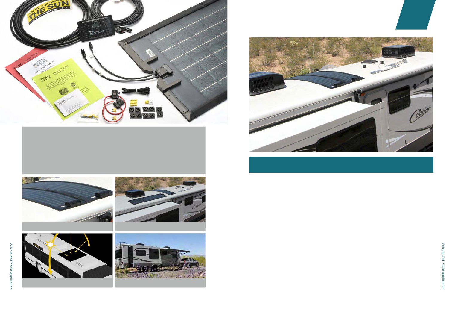
Flexible panels applied to trucks / containers / refrigerated trucks
Flexible panels applied to RV market
Flexible panels applied to traveling vehicles and ships
3.5
Vehicle and yacht applications
77
